
Construction document sets form the backbone of project delivery in architecture, engineering, and construction. These documents are not only a reflection of design intent but also function as the legal and technical basis for execution. Whether in public infrastructure or private real estate, a well-prepared document set facilitates seamless collaboration between consultants, contractors, regulatory agencies, and clients.
Every construction document set fulfills two core responsibilities: satisfying authority requirements and addressing client-specific goals. Building codes, safety regulations, environmental standards, and accessibility guidelines must be embedded clearly within the documentation. Simultaneously, client expectations around design aesthetics, functional layouts, material quality, and operational needs are translated into detailed, buildable instructions that guide project teams through execution.
AEC workflows follow a structured design phase progression Schematic Design, Design Development, and Construction Documentation. Each stage increases the depth and coordination of information. Once the documents reach the Good For Construction stage, they support smooth permitting, bidding, and on-site implementation. Well-coordinated GFC packages improve clarity across disciplines, enable proactive planning, and strengthen confidence among stakeholders throughout the project lifecycle.

Why Design Phases Are Essential in Construction Projects
Phased design workflows are foundational to managing risk, coordination, and regulatory alignment in architecture and construction. These stages allow firms to engage consultants at the right time, integrate authority feedback early, and maintain cost visibility as technical complexity increases. Rather than treating the design process as a single event, phase-based development ensures that each layer of decision-making, from spatial planning to engineering integration. It is validated before construction readiness. This method is especially critical in large-scale or multi-use projects where approvals, permitting timelines, and client milestones must be strategically aligned.
Core Design Phases in AEC Workflow:
- Schematic Design
- Design Development
- Construction Documentation
Schematic Design establishes space planning and zoning within site and code constraints. Design Development introduces consultant coordination and material systems while supporting budget alignment. Construction Documentation converts all prior inputs into a comprehensive, permit-ready package that addresses construction logistics, authority approvals, and trade sequencing. This structured progression minimizes rework, supports bid accuracy, and keeps project momentum aligned with client goals and regulatory deadlines.
Schematic Design Phase: Laying the Foundation
The Schematic Design phase in AEC projects is where the project team establishes key design parameters to address site constraints, project briefs, and regulatory boundaries. Instead of simply presenting sketches, architects use this phase to validate the maximum buildable area, align massing with fire and access codes, and pre-calculate vertical circulation strategies based on occupancy requirements. Zoning overlays, height limits, and initial Floor Space Index studies are layered into early spatial layouts. Consultants may be brought in to advise on shaft sizing, plant area estimates, or utility corridor planning, ensuring the conceptual layout supports technical feasibility.
Client engagement during SD goes beyond visual preference; it focuses on evaluating multiple operational models, adjacency plans, and commercial fit-outs within a permitted envelope. Key outputs often include program-stacked block diagrams, site utilization studies, draft parking schemes, and optional façade directions. These are supported by basic sun path, wind flow, and service ingress studies for client review. A well-executed SD package enables faster internal alignment, early authority consultations, and a framework for cross-disciplinary design coordination in the following phase.
Design Development Phase: Refining the Design
Design Development transitions the conceptual layout into a technically grounded, spatially coordinated design. In this phase, the architecture is detailed to accommodate structural systems, vertical circulation, MEP services, and building envelope strategies. Slab offsets, beam depths, core wall thicknesses, and riser shafts are validated through collaborative workshops with consultants. Wall assemblies, fire-rated zones, ceiling heights, and service routes are defined with enough specificity to identify spatial conflicts early. Critical design choices like HVAC zoning, structural framing logic, and façade system types. These are resolved to a level that allows preliminary cost planning and design freeze for regulatory submission.
Client reviews during DD are highly focused, with discussions centered on functional layouts, operational adjacencies, and material alignment with the project’s intent and budget. Deliverables include coordinated floor plans, key sections, preliminary reflected ceiling plans, and wall build-up diagrams. Material specifications, fixture schedules, and equipment loads are outlined to support MEP load calculations. This phase includes the first fully coordinated BIM model, serving as a live reference for value engineering, design validation, and authority inputs before the final construction documentation begins.
Scope of a Standardized Construction Document Set in AEC
Construction documentation in the AEC industry is tailored not just for design clarity but to support coordination across contracts, consultants, site teams, and reviewing authorities. Each document type is structured to align with the project’s delivery strategy, whether it’s a Design-Bid-Build contract requiring separate bid packages or a Design-Build model demanding integrated consultant input. Document sets also follow the project’s maturity level in BIM workflows, with LOD 400 for execution and LOD 500 for as-built and facility use. Structured deliverables help streamline permissions, minimize scope ambiguity, and provide the technical foundation for vendor coordination and shop drawing development.
Key Deliverables in a Standard AEC Construction Document Set:
- Architectural Sheets: Detailed floor plans, GFC sections, elevations, internal partitions, finish plans
- Structural Packages: Reinforcement details, foundation layouts, framing systems, RCC/steel assembly plans
- MEPF Drawings: Service layouts with coordinated shaft positions, pipe sizing, ducting, cabling, and fixture locations
- Schedules: Doors, windows, equipment, light fixtures, room finishes, and hardware
- Technical Specifications: Product standards, workmanship clauses, system performance requirements
- LOD 400/500 BIM Extracts: Federated models and discipline-specific views ready for coordination or fabrication
Mapping Documents to Regulatory Requirements
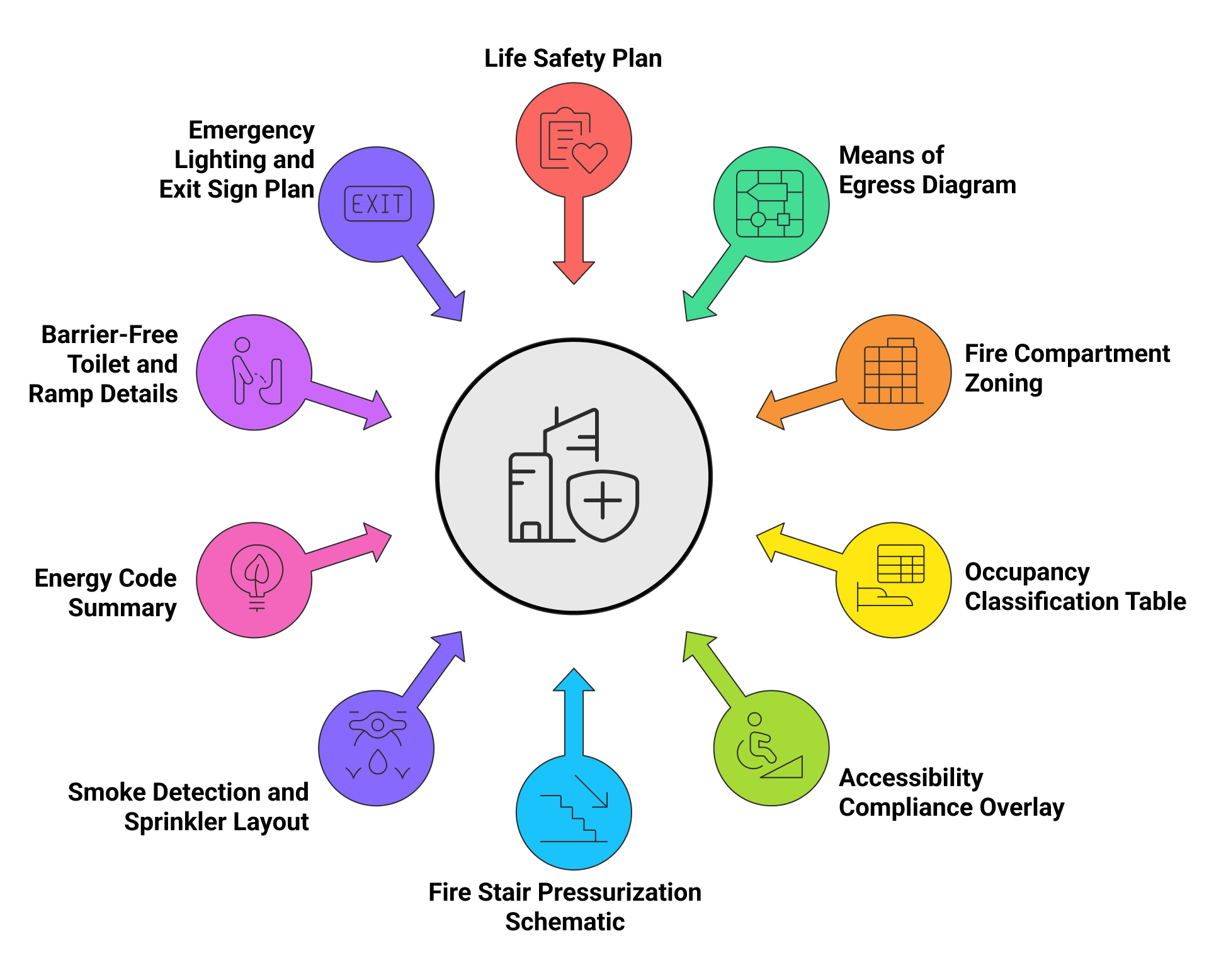
Construction documents are formatted to satisfy both national building regulations and the unique submission requirements of local authorities. Each drawing sheet is embedded with prescriptive and performance-based code data such as fire compartmentation boundaries, HVAC zoning logic for pressurization, and ADA-compliant clearances. Code sheets are not stand-alone; they are interwoven into architectural and engineering packages to provide direct visual and annotation-based compliance evidence. This integration allows stakeholders, including municipal reviewers and fire safety officers, to verify compliance directly from design documentation without external clarification.
Projects must demonstrate proactive alignment with codes like NBC 2016, ASHRAE 90.1, ECBC 2017, and local development control regulations. Typical deliverables include coordinated life safety overlays with stair pressurization details, occupancy calculations tied to built-up area charts, and ECBC-compliant energy modeling highlights. Accessible paths, signage placement, and rescue area demarcation are mapped at a sheet level, with jurisdiction-specific submittal formatting such as approval stamp zones, color-coded phasing, and bilingual legends; factored into the document layout. These deliverables reduce approval timelines and provide confidence to both authorities and project clients.
Code-Related Elements for Regulatory Sheets:
Client-Centric Structuring of Documentation
Step 1: Align Drawing Scope with Tenant vs. Shell-Core Responsibilities
Before documentation begins, project teams define ownership boundaries between landlord-provided shell-core elements and tenant interior scope. Separate drawing packages are generated for each, ensuring that shell permits, lease agreements, and tenant improvements are processed independently yet compatibly.
Step 2: Embed Client-Fitout Elements into Primary Drawings
Client-specific interventions such as premium lobby materials, acoustic zones, branding walls, or proprietary lighting systems. These are embedded into GFC drawings rather than treated as post-design add-ons. This improves coordination and reduces cost escalation during construction.
Step 3: Milestone Packages Structured for Decision-Gated Approvals
Each documentation phase is prepared to match the client’s internal approval checkpoints—like “Schematic Freeze,” “Pre-GFC Review,” or “Procurement-Ready IFC.” These document sets include side-by-side alternates and color-coded annotations that streamline client review workflows.
Step 4: Apply Document Layering for Parallel Review Streams
Large-scale or multi-phase projects often require different sets to be reviewed by different teams: leasing agents, facility managers, and branding consultants. Customized layering strategies allow architectural sheets to be filtered by trade, scope, or decision category.
Step 5: Integrate Build Standards and Custom Signage Protocols
Client-provided build guides, such as retailer prototype standards or hospital room layouts, are translated into compliance matrices within the drawing set. Signage zones, tactile paths, and wayfinding schemes are also included for projects where brand experience and navigation are critical.
Coordination Strategies for Discipline-Specific Documentation
- Separate drawing sets are created per discipline to avoid overlapping responsibilities.
- Sheet naming follows structured prefixes like A, S, MEP-FP for easy navigation.
- BIM clash detection tools resolve service intersections before IFC issue.
- Discipline-specific filters and views streamline review of complex models.
- All consultant files are linked into a central model to maintain design alignment.
- Specialty consultants follow pre-assigned sheet ranges to prevent duplication.
- Floor plans are split into coordination zones to manage trade overlaps.
- Vertical cores and shaft drawings isolate dense service areas for clarity.
- Annotations are divided logically to prevent scope confusion between trades.
- Coordination logs track sign-offs and revisions ahead of final documentation.
QA/QC Protocols in Final Documentation
Before final release, construction document sets go through multi-layered QA/QC protocols led by discipline leads, BIM coordinators, and quality managers. Each drawing sheet is reviewed for alignment between annotation and modeled elements, while key GFC deliverables are validated against the client brief and regulatory checklist. Tools like BIM 360 Model Checker and Solibri automate checks for untagged elements, misaligned annotations, and fire zone violations. Coordination logs ensure that consultant inputs are clash-free and verified zone-wise. Version-controlled submissions with documented issue resolution history form the audit trail for design integrity, ensuring the issued set meets both client-specific scope and authority approval norms.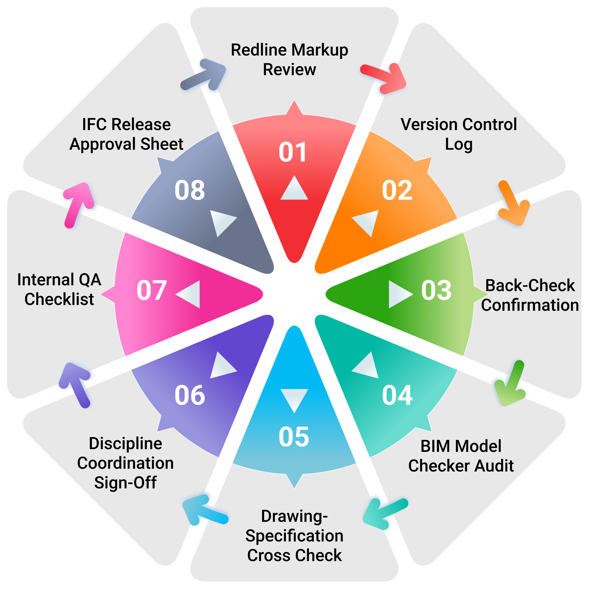
Causes of Rejection by Review Authorities
- Fire exit widths not matching local NBC/NFPA guidelines across floors
- Incorrect occupancy classification in code summary sheets
- Egress paths drawn without door swing or exit signage details
- Fire hose reel locations missing from life safety floor plans
- Energy compliance summary missing ECBC envelope U-value tables
- Incomplete accessibility diagrams for toilets, ramps, or tactile routes
- Drawings submitted without municipal CAD layer standards
- Structural general notes not referencing IS 456 or local seismic zoning data
- AHJ approval block missing from title sheets or key plans
- Permit sets containing IFC-level detailing instead of simplified review format
- Elevation markers and datum lines inconsistently placed across sections
- Submission without checklist alignment to state-specific green building mandates
Digital Platforms Supporting Compliant Documentation
Digital platforms like Autodesk Docs and BIM 360 enable structured GFC document management with controlled access and approval workflows. Revit ensures model-linked drawings reflect real-time updates, while Revizto allows consultants to mark up coordinated sheets for faster resolution. Solibri Office supports automated compliance checks, and CDEs following ISO 19650 standards help maintain consistent file naming, metadata, and submission formats, ensuring documentation remains precise, organized, and aligned with regulatory expectations.
Deliverable Handoff and Project Record Finalization
The final stage of documentation involves organized handoff of approved deliverables and structured project record creation. AEC teams prepare a digital package that includes GFC drawings in PDF and DWG formats, federated IFC models, specification sheets, and discipline-wise as-built markups. These deliverables are often compiled using Common Data Environments to ensure version traceability and metadata clarity. Project closeout also includes updated redline drawings based on on-site changes, coordinated consultant packages, and structured folders aligning with client turnover protocols. Teams use standardized formats such as COBie and ISO-aligned asset logs to support operations, maintenance, and future renovations, reinforcing long-term usability of the document set.
Conclusion
A well-executed construction document set does more than guide construction; it builds trust across regulatory bodies, contractors, and clients. By aligning documents with compliance standards, client-specific requirements, and project delivery models, AEC firms support faster approvals, smoother coordination, and fewer on-site uncertainties. Precision in documentation reflects a firm’s commitment to quality, accountability, and technical excellence. Leveraging BIM tools, clash detection, QA protocols, and integrated workflows ensures every sheet issued supports clarity, constructability, and regulatory readiness from concept to closeout.