Mechanical and electrical systems now occupy more space and demand greater coordination than ever before in high-density AEC projects. From large-diameter ductwork sharing plenum space with bundled cable trays to electrical switchgear installed alongside mechanical risers, these systems are no longer isolated scopes; they’re overlapping and interdependent. Mechanical Modeling and Drawings help visualize and coordinate these complex systems early in the design process. As buildings become more service-intensive, such as in hospitals, airports, and commercial towers, MEP trades face increasing pressure to coordinate every route, clearance, and access point without delays or rework.
Conventional coordination methods like 2D layering, PDF markups, and post-design RFIs fall short in resolving real spatial constraints on-site. Multiple subcontractors working in silos often lead to overlapping service zones, unclear routing priorities, and last-minute field changes. Even with well-developed drawings, mechanical and electrical contractors struggle with constructability when clearances are missed, shafts are overfilled, or sequencing logic breaks down during installation. Electrical Modeling and Drawings, along with their mechanical counterparts, provide a more integrated approach to identifying and resolving these issues early. These gaps create costly ripple effects across schedules, procurement, and labor efficiency.
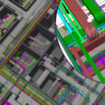
BIM introduces a model-based coordination environment where each trade’s layout is integrated into a single federated model, enabling early detection of system clashes and spatial inefficiencies. Instead of reacting to issues in the field, contractors use BIM to coordinate duct banks, cable trays, riser terminations, and equipment zones during the preconstruction phase. MEP Drawings generated from the model support this process by providing clear, up-to-date documentation that reflects coordinated design intent. The goal is to build smarter, faster, and more collaboratively by using digital workflows to align trades and reduce rework before work begins on site.
Limitations of Traditional Coordination Methods
On many large AEC job sites, mechanical and electrical contractors are still handed 2D coordination drawings that don’t account for on-site spatial realities. Each subcontractor often prepares their layouts based on separate sets of assumptions, without real alignment to actual riser sizes, structural interferences, or sequencing logic. When multiple trades converge in high-congestion areas like corridor ceilings or service cores, clashes between ductwork, cable trays, and structural elements become unavoidable. Without a spatially intelligent model, teams discover too late that there’s no space left for insulation, access panels, or future expansion routes. These errors aren’t just inconvenient; they trigger fabrication delays, change orders, and emergency design revisions.
Even when drawings appear coordinated, traditional workflows struggle to reflect the step-by-step reality of how systems will be installed. A duct route may look feasible on paper, but fail on-site when electrical gear is placed first or access to a panel is blocked by piping. RFIs and manual redlines can’t keep up with this dynamic reality on fast-track projects. The inability to simulate trade sequencing or visually verify constructability results in lost time, strained subcontractor relationships, and a flood of reactive coordination meetings. In this environment, even well-planned systems underperform simply because they were never coordinated in 3D before construction began.
BIM as the Coordination Backbone for MEP Trades
BIM brings clarity and control to MEP coordination by allowing mechanical and electrical contractors to work within a shared spatial environment where every route, clearance, and system dependency is accounted for. Each trade develops its scope-specific model based on verified geometry, code compliance, and known constraints, eliminating guesswork and overlap. When models are brought together, spatial ownership becomes defined, reducing scope creep, layout conflicts, and late-stage rerouting. Instead of reacting to site conditions, contractors use BIM to make informed layout decisions during coordination, enabling smoother transitions to shop drawings and installation.
The process is driven by a clear BIM Execution Plan, which outlines modeling responsibilities, trade priorities, tolerances, and handoff schedules. Coordinated reviews are conducted at fixed intervals, where models are federated and clash reports are run. These reviews aren’t just visual checks; they’re decision points that influence fabrication, procurement, and field sequencing. Mechanical and electrical teams gain alignment on routing logic, equipment zones, and hanger coordination, helping prevent downstream disruption. BIM becomes more than a 3D tool; it becomes the live reference for how systems are planned, built, and delivered.
Pro Tip: Assign spatial priority by system type and zone early in the project. This eliminates unnecessary negotiation during coordination and accelerates approvals for downstream trades.
Key Benefits of BIM for Mechanical and Electrical Coordination
Clash Detection and Constructability Validation
Instead of identifying conflicts during installation, BIM allows mechanical and electrical contractors to detect route clashes, clearance violations, and access zone conflicts at the modeling stage before shop drawings are issued. Common issues like overlapping duct and conduit paths in risers or undersized equipment rooms are flagged and resolved through structured clash reviews. This prevents rework in zones that typically require re-routing, like ceiling junctions and back-of-house rooms, and gives contractors more time to coordinate lead time-sensitive equipment layouts.
Visualization and Stakeholder Communication
In multi-trade coordination meetings, contractors often struggle to explain layout constraints using 2D views alone. BIM solves this by making it possible to walk stakeholders through ceiling congestion, shaft build-outs, or MEP/architectural trade-offs in real-time. When a change affects duct clearance over a lighting grid or conduit access behind wall finishes, BIM allows all parties including field teams and PMs to see the issue clearly and agree on solutions without relying on interpretation-heavy sketches or markups.
Prefabrication and Installation Accuracy
On-site coordination issues can stall prefabrication unless models are truly install-ready. BIM allows mechanical and electrical teams to extract spool-ready layouts that reflect hanger spacing, insulation offsets, and bracket details based on coordinate geometry. This eliminates the need for cutting or adjusting in the field and reduces the number of components that are shipped incomplete or incorrectly routed. Prefab teams gain confidence that what they build will install without last-minute patchwork.
Construction Sequencing and Logistics
BIM brings sequencing clarity into trade coordination in zones where install order affects access. Mechanical duct risers can’t be boxed in by early conduit runs, and access zones around panels or valves must remain untouched. With 4D BIM, logistics teams can plan delivery routes, installation priorities, and vertical stacking with input from all trades. This reduces standdowns on-site when one system blocks another’s path, and helps maintain clean floors during critical install windows.
Centralized Real-Time Collaboration
When multiple trades submit revisions separately, coordination breaks down quickly. BIM tools like Autodesk Construction Cloud and Revizto offer a single, live model space where electrical and mechanical teams can review changes, log issues, and close them out without waiting for offline clash reports. Comments tied to exact locations allow field leads and BIM managers to discuss routing logic without walking the site. This speeds up decision-making and reduces delays between coordination and field updates.
Reduction in Waste, Errors, and Rework
Errors in ceiling layout or shaft routing often result in wasted brackets, re-ordered hangers, or torn-out conduit runs. BIM helps prevent these by locking spatial zones before procurement and giving field teams coordinated install instructions. Since models account for access paths and mounting levels, there’s less confusion during install, fewer late-scope changes, and minimal material overordering. Field supervisors benefit from clear sequencing, avoiding “trial and error” fitting in tight zones.
Lifecycle and Facility Management Support
Many MEP models are discarded after handover but coordinated BIM workflows allow mechanical and electrical data to live on as part of a digital twin. Contractors can tag equipment with asset metadata, O&M links, and spatial context, giving facility teams clear visual records of access zones, maintenance paths, and shut-off points. This is critical in projects like hospitals and airports, where emergency access or service continuity relies on knowing exactly what’s behind walls and above ceilings.
BIM-Enabled Workflow for MEP Coordination
Step 1: Define Routing Zones and Trade Priorities
At the start of coordination, zones are assigned for mechanical and electrical systems in shafts, ceiling spaces, and risers. System priority is determined based on size, criticality, and sequencing needs. This helps avoid routing conflicts later and gives each trade clarity on where and how to model.
Step 2: Model Based on Construction Logic
Each trade models its systems in alignment with how they will be installed in the field. Mechanical teams focus first on mains, risers, and equipment connections. Electrical teams focus on panel layouts, containment routes, and clearance requirements. Field constraints such as access panels, valve reach, and mounting heights are built into the model from the start.
Step 3: Run Internal Trade Checks Before Submission
Before sharing their models for coordination, trades perform internal model checks. Mechanical teams verify duct clearances, support locations, and flange spacing. Electrical teams model conduit spacing, maintain routing continuity, and include equipment service zones accurately.
Clean models reduce wasted coordination time and improve meeting productivity.
Step 4: Aggregate Models for Clash Detection
All trade models are federated into a single coordination model using tools like Navisworks or BIM 360. Clash detection is focused by zone or system type to reduce unnecessary data. Coordination teams prioritize areas where routes overlap, like tight corridors, cores, and equipment rooms, to resolve issues early.
Step 5: Resolve Issues in Active Coordination Sessions
Coordination meetings focus on a defined set of high-impact issues. Trades review conflict areas with the BIM coordinator using shared model views. Each clash is assigned to a responsible party with a resolution deadline. Adjustments are made directly to the model or discussed for follow-up revisions.
Step 6: Zone-by-Zone Sign-Off for Fabrication
Once a zone is fully coordinated and reviewed by all trades, it is approved for drawing extraction. Shop drawings, hanger layouts, and spool sheets are generated only from approved zones. This phased sign-off process supports ongoing fabrication and reduces the risk of downstream changes.
Step 7: Site Execution and Feedback Integration
Coordinated models are used for field layout with digital tools like Total Stations. Install crews mark points, verify routes, and flag any access issues or design gaps. Field updates are captured as markups or issue logs and shared back with the BIM team. These updates are integrated into the as-built model for accurate recordkeeping and final turnover.
Challenges in BIM Coordination
- BIM models often lack mounting details, making field installation unclear.
- Some subcontractors treat coordination as a design task rather than a buildability review.
- Tight coordination schedules leave little time for internal model QA.
- Modeling teams rarely get site feedback, so constructability issues repeat across zones.
- Trade priorities are not enforced, leading to repeated rerouting during clash resolution.
- Hanger and support coordination is often skipped, causing real-world install conflicts.
- Sleeve and core cutout requests are issued without spatial verification, leading to structural clashes.
- Equipment clearance zones are modeled but later violated by adjacent trades.
- Late model updates from consultants force downstream trades to re-coordinate finished zones.
- BIM managers are often overloaded, delaying issue tracking and clash review cycles.
- Field teams don’t always have access to the latest coordinated model on-site.
- Some field installers still rely on 2D drawings, ignoring critical spatial constraints in the model.
- High-detail LOD slows model performance, but simplifying too early causes accuracy loss.
- Asset tagging is often incomplete, reducing model value for facility management.
- Clash reports flag hundreds of issues but lack prioritization or resolution deadlines.
Conclusion
BIM-enabled coordination strengthens the reliability of MEP deliverables by integrating spatial validation, system-level clash detection, and construction-driven model reviews into the preconstruction phase. Mechanical and electrical contractors benefit from digitally assigned routing hierarchies, verified clearance zones, and LOD-controlled outputs that directly support prefabrication and on-site layout. With coordinated BIM workflows, trades can execute with greater precision, reduce field-generated RFIs, and maintain alignment with installation sequencing. As AEC projects increasingly demand compressed timelines, tighter tolerances, and just-in-time logistics, adopting model-based coordination becomes a core strategy for delivering high-performance systems with reduced rework, improved productivity, and better cost predictability.