
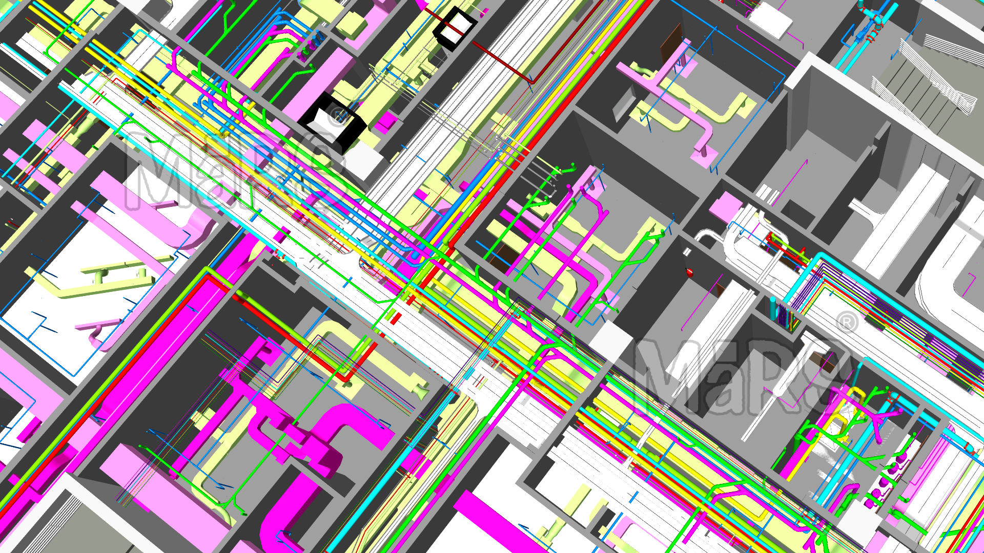
HVAC duct systems are tightly integrated within MEP networks, routed through congested ceiling voids, vertical shafts, and mechanical zones. Every linear foot of duct must navigate structural beams, fire-rated walls, and a web of parallel trades, each with their own spatial and code-driven constraints. Duct routing decisions directly impact airflow efficiency, equipment performance, and serviceability over the building’s lifecycle.
Contractors operate in environments shaped by early prefabrication, digital coordination, and rigid sequencing milestones. Mechanical scopes are released for fabrication only after duct layouts are validated against electrical trays, sprinkler pipes, and structural openings. HVAC duct shop drawings provide this validation, detailing duct dimensions, insulation allowances, hanger points, access panels, and transitions as per field-verified coordination.
These drawings form the technical foundation for field execution. Foremen use them to locate hangers before slab casting. Fabricators use them to cut sections and label packages by zone. Project engineers use them to track progress, issue RFIs, and conduct QA reviews. Precision in drawings supports faster installation, reduces risk, and improves coordination across every phase of MEP execution.
What Are HVAC Duct Shop Drawings?
HVAC duct shop drawings are the final, constructible outputs that contractors use to guide on-site installation and off-site fabrication. Developed post-coordination, these drawings embed field-specific data duct sizes with insulation offsets, flange-to-flange dimensions, support rod details, damper placements, and connection types aligned with system pressure class. They account for slab penetrations, wall sleeves, coordination offsets, and precise hanger rod drop points, offering layout certainty before any duct leaves the workshop or reaches the jobsite.
Produced by BIM modelers or MEP detailers and reviewed by site engineers, these drawings are directly tied to installation sequence and spatial logic. HVAC contractors use them to lock in insert placement before concrete is poured, while fabrication shops use them to batch and label ductwork per floor or zone. Unlike generic design layouts, It reflect decisions made during clash detection, trade sequencing, and RFIs making them essential tools for delivering an error-free HVAC scope within compressed construction timelines.

Shop Drawings Are Execution Tools
Duct shop drawings are treated on-site as construction directives. These drawings include dimensionally locked duct paths adjusted for coordinated zones, slab-to-slab elevations, anchor bolt positions and exact hanger rod drops referenced from structural steel or PT slab layouts. Field crews use them to pre-mark hangers, verify shaft space occupancy, and sequence installations in zones with zero tolerance for adjustments. Every drawing communicates trade-specific instructions identifying fire-rated assemblies, damper codes, turning vanes, access panel directionality, and clearance envelopes for service. Without this level of precision, foremen face guesswork during installation, and prefabrication teams risk misaligned deliveries. These drawings transform coordination data into site-ready, build-verified instructions that directly support error-free execution.
The Role of Coordination in Tight MEP Corridors
HVAC duct routing in multi-trade corridors often comes last in priority after structural, plumbing, and electrical systems. By the time ducts are routed, only fragmented space remains above ceiling grids or in service shafts with limited vertical clearance. It integrate spatial constraints resolved during clash detection, reflecting negotiated duct elevations, rolled offsets to avoid sprinkler lines, and adjusted dimensions to preserve minimum airflow velocity in constricted runs.
Contractors rely on these drawings to finalize insert locations for hanger rods before slab casting and to coordinate with fire-stopping teams for rated wall penetrations. Duct segments are often staggered to clear large cable trays or routed behind bulkheads to maintain headroom. These field-driven adjustments only appear in shop drawings, making them essential for actual constructability within the tight logic of MEP sequencing.
Benefits to Contractors
Accurate Installation Guidance
Site teams use drawings to chalk hanger locations before slab casting and align duct drops with embedded sleeves. These drawings include flange-to-flange dimensions, rod drop heights from soffit, and transitions sized to fit pre-defined shafts, ensuring installers follow exact routing without field modification.
Clash Detection and Resolution
Ducts passing through congested risers or low ceiling zones are adjusted during coordination, and the resolved paths are captured in shop drawings. For example, a 600×400 mm duct might be reshaped to an oval or split into dual runs to clear cable trays, decisions impossible to make on site without prior resolution.
Time and Cost Efficiency
Installers sequence duct drops zone-wise using drawings marked with zone IDs and elevation stamps. Fabrication is planned around approved routes, reducing idle time on site, minimizing hot works, and avoiding wasted sections due to misalignment with beams or offsets.
Compliance and QA
Drawings define rated wall penetrations with fire collar codes, damper schedules per floor, and airflow labels per duct segment. QA teams use them to inspect fire barrier sealing, verify insulation specs, and check damper placement before sign-off, avoiding failed inspections or change orders.
Communication and Accountability
When electricians or plumbers route over agreed duct zones, this drawings serve as the baseline to resolve conflicts. Contractors use them during coordination meetings to confirm trade boundaries, identify installation order, and prevent scope creep across subcontractors.
Power Off-Site Prefabrication
Duct shop drawings are used to generate spool sheets for fabrication, detailing duct lengths that fit within truck bed constraints, flange orientations for quick bolting, and damper insertion points tied to fire zone schedules. Fabricators follow these drawings to pre-assemble sections with turning vanes, stiffeners, and sealant specs applied as per pressure class, ensuring the assemblies land on-site ready to install. When drawings don’t reflect field-resolved offsets, like a 100 mm drop to clear a slab beam, ducts arrive unusable, triggering costly rework or overnight re-fabrication. Zone-based packaging, tied to drawing markups, allows teams to deliver duct kits floor by floor, aligning material drops with crane schedules and install sequences. This level of logistical precision is only possible when drawings are tightly integrated with fabrication workflows.

Site Teams Build from Shop Drawings
Site teams follow HVAC duct shop drawings as their primary reference during installation; design documents are rarely used once construction begins. These specify duct start and end elevations, sleeve centerlines, rod anchor positions relative to gridlines, and duct weights for hanger load checks. Foremen mark hanger inserts directly from these drawings before slab pouring, while installers use them to align duct flanges with structural embeds or pre-installed services. Details like riser offsets to avoid door headers or soffit drops to maintain ceiling heights are finalized in these drawings, not in design plans. By locking in field-verified dimensions and routing decisions, It ensure duct systems are installed without guesswork, misalignments, or delays caused by recoordination on site.
Avoiding Specific On-Site Errors
- Incorrect sleeve locations fixed early with grid-aligned duct centerlines.
- Duct flanges adjusted to clear pre-installed electrical bus ducts.
- Fire damper access doors aligned before partition closure.
- Rod drops matched to cast-in anchor positions with exact slab offsets.
- Duct sizes coordinated to bypass structural or MEP obstructions.
- Tapered transitions tagged to avoid reversed fabrication.
- Damper assemblies resized to rotate into tight shaft spaces.
- Trade sequencing zones defined to prevent corridor-level clashes.
Execution-Based Best Practices for Contractors
- Request coordination lock-in for duct zones before embed layout begins.
- Cross-check duct-to-slab clearance against measured soffit drop onsite.
- Use trade-colored layering to separate systems visually during review.
- Confirm hanger loads and anchor types based on duct weight tables in drawings.
- Tag shaft ducts with lift sequence codes for vertical install planning.
- Review access door swing directions relative to partition build-outs.
- Align sleeve tags with RCP lighting layouts to avoid fixture conflicts.
- Include damper inspection clearances directly on detail callouts.
- Run field walk with foremen using printed drawings before fabrication release.
- Stamp drawings only after field lead signs off on coordination-critical dimensions.
Cross-Trade Coordination Strategies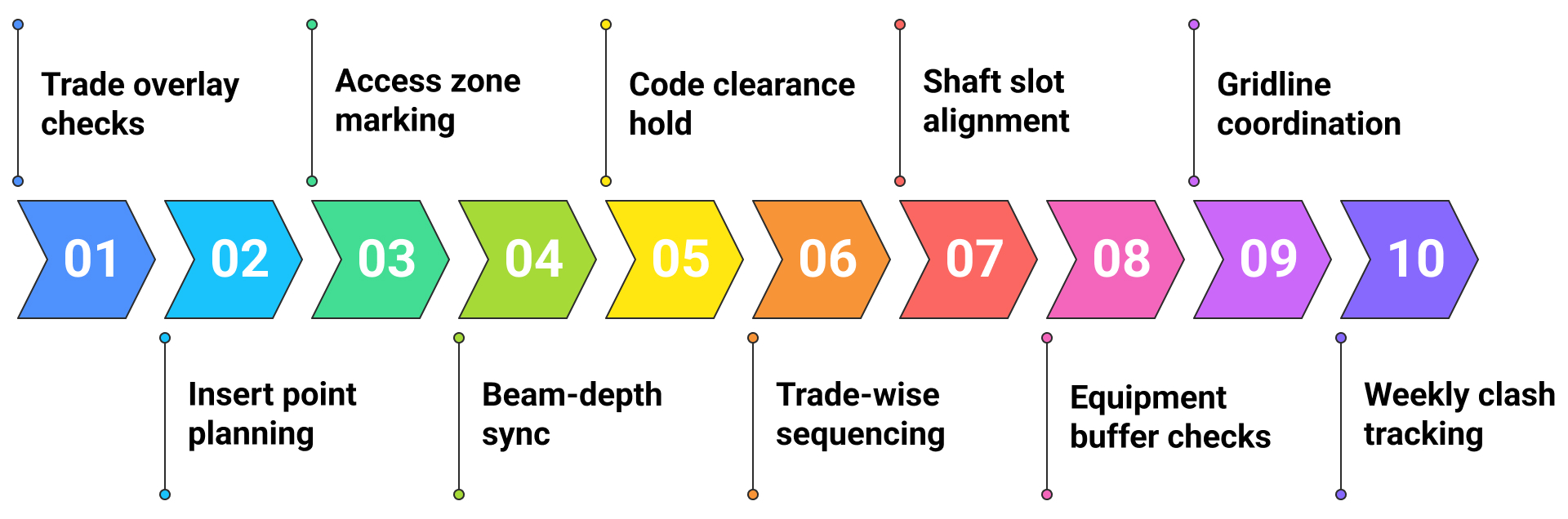 Quality Control in Production
Quality control in production ensures constructability, code compliance, and fabrication accuracy. Duct sizing must align with airflow requirements and equipment specifications, while all fittings, offsets, and transitions should reflect coordinated model geometry. Elevation mismatches, conflicting annotations, or missing tags are red-flag issues caught during QA review cycles. Coordination teams cross-check drawings against the latest clash-resolved BIM models and structural grids to verify spatial compliance. Final review involves input from BIM leads, project engineers, and site foremen to confirm that hanger positions, damper placements, and sleeve references match actual site constraints before issuing for construction or fabrication.
Conclusion
Shop drawings translate HVAC system designs into actionable, build-ready plans that align with on-site conditions, spatial constraints, and coordinated MEP layouts. For contractors, these drawings drive precise duct routing, streamline prefabrication, and anchor installation sequencing across tight construction schedules. When developed through detailed BIM coordination and validated against real-world site data, It become central to achieving faster installations, minimized clashes, and smoother handovers, all with measurable cost and time gains.