MEP BIM Coordination
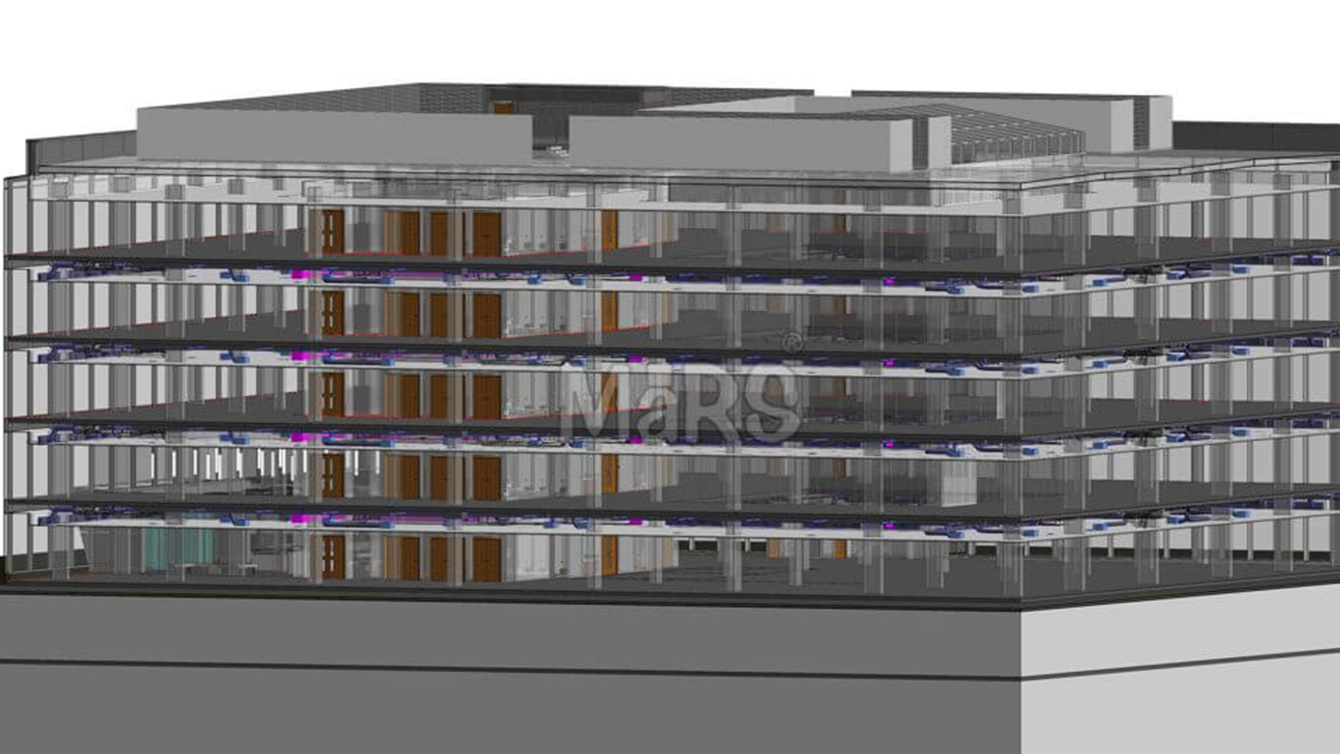
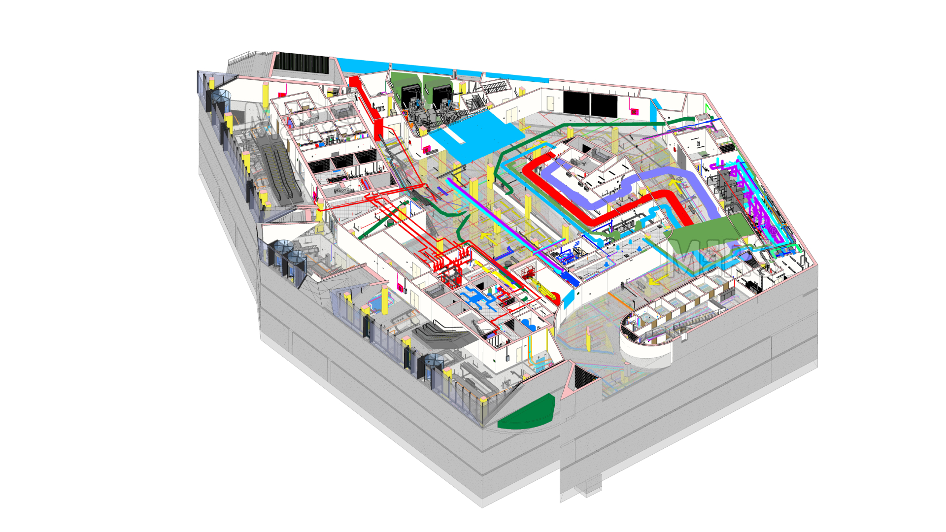
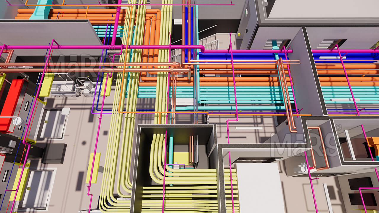
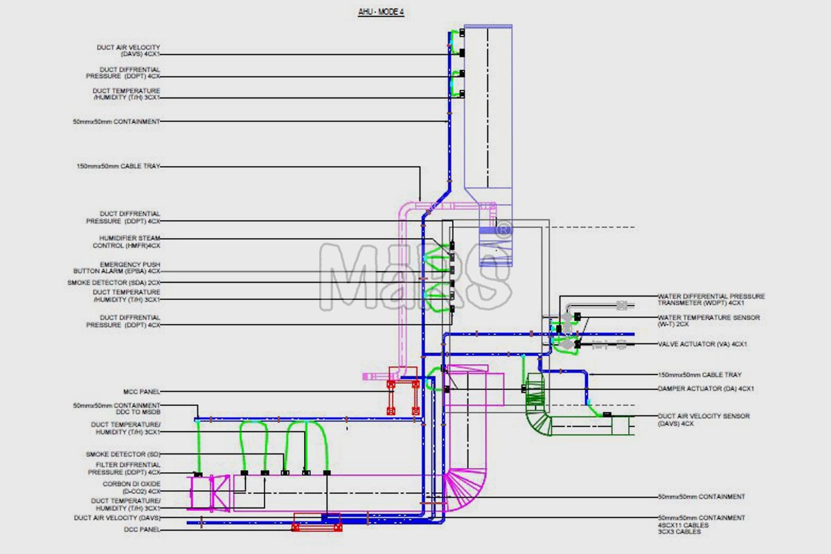
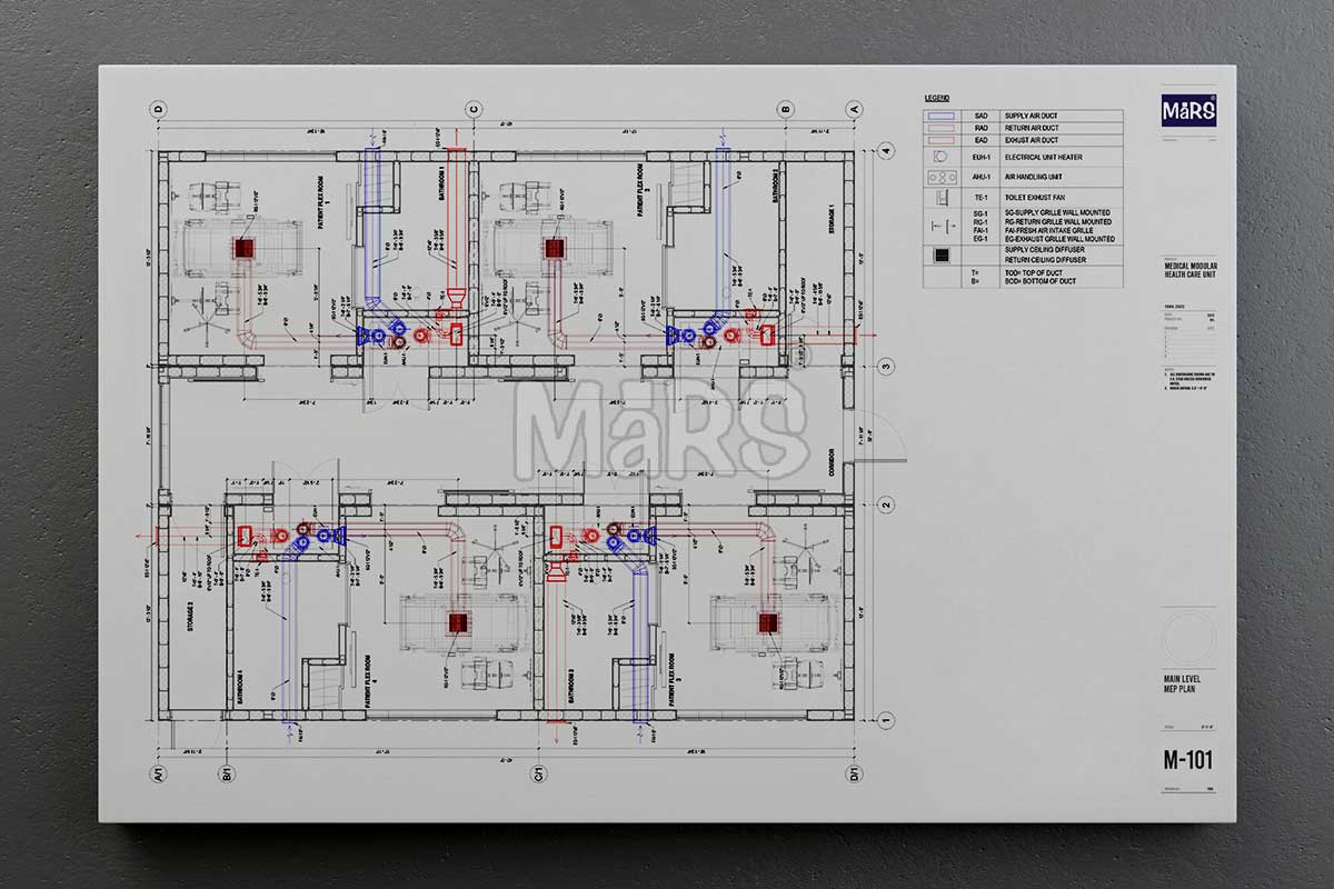
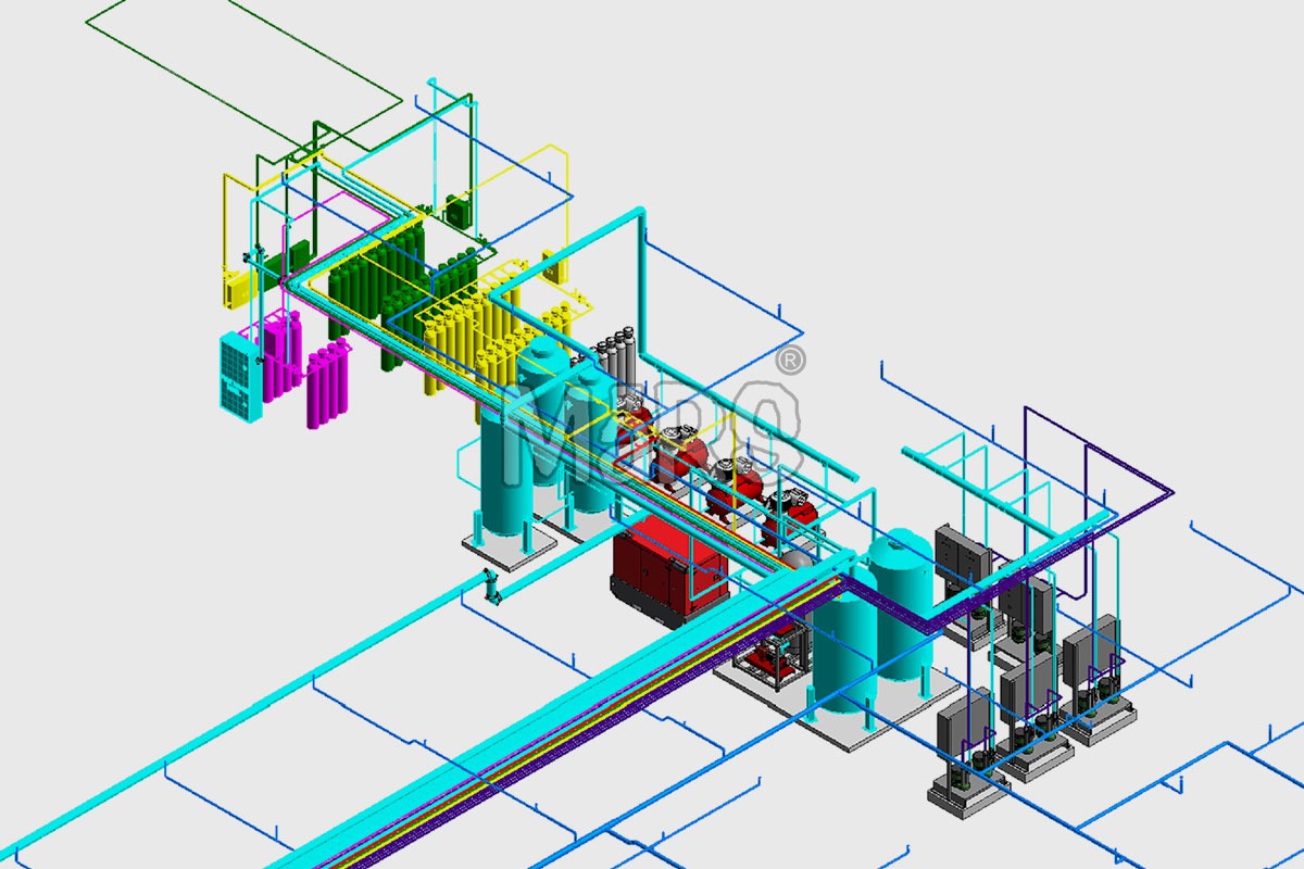
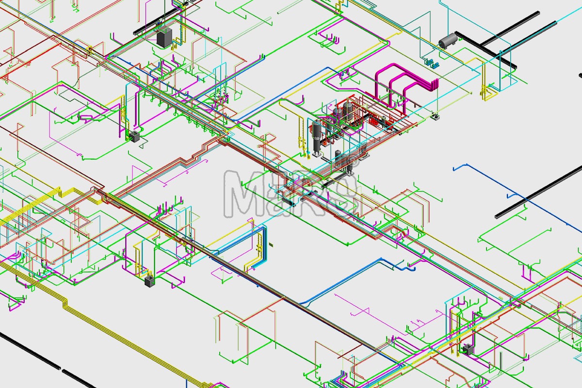
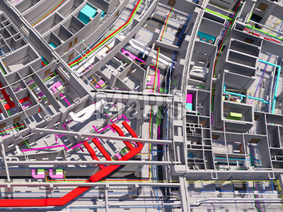
We provide MEP Coordination services to manage Mechanical, Electrical, and Plumbing systems. Using BIM, we detect clashes, resolve issues, and ensure accurate coordination. This helps speed up the project, lower costs, and improve quality.
MEP Coordination That Eliminates Field Conflicts
We work across commercial, healthcare, data center, aviation, and infrastructure sectors, bringing the same coordination standard to every project regardless of size or complexity. Our coordination process is built around one outcome: every MEP system fits, every trade knows exactly where their scope goes, and construction release happens on schedule.
Our Approach
We use Autodesk Revit for trade modeling, Navisworks for systematic clash detection, and Autodesk Construction Cloud for live model collaboration across all project stakeholders. But the tools are only part of it. What separates our coordination from a standard clash report service is how we manage the process from model intake to signed construction release.
Every project starts with a model validation phase. Before we run a single clash test, we review each trade model for geometry errors, coordinate misalignments, and missing elements that would produce false results. This step alone eliminates a common source of wasted coordination rounds.
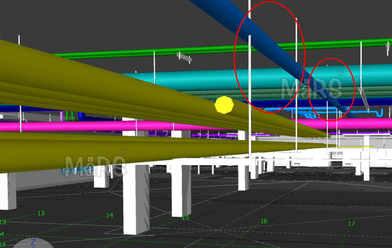
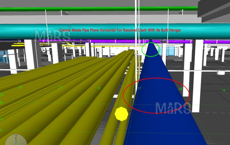
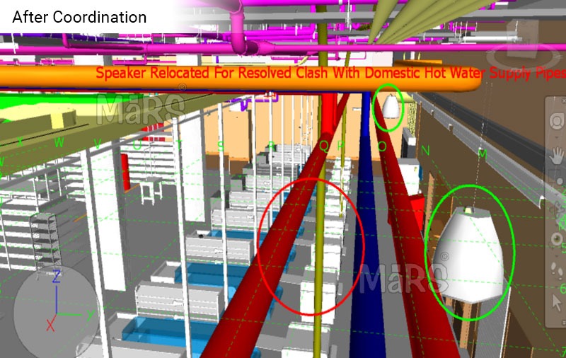
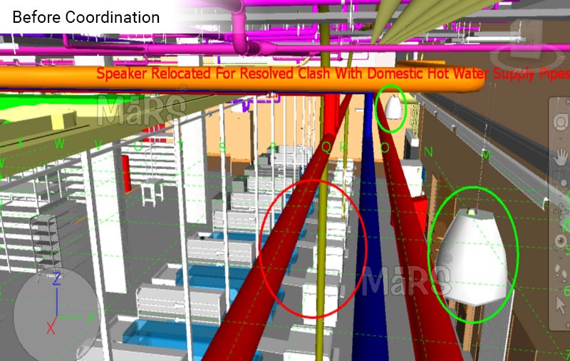
We run clash detection across hard clashes, clearance clashes, and workflow clashes using project-specific tolerances defined in the coordination protocol, not generic software defaults. Every conflict is catalogued in a structured clash matrix, assigned to the responsible trade, tracked through resolution, and signed off before the zone moves to construction release.
Our in-house team includes MEP engineers, BIM coordinators, and VDC specialists who work together on every project. We facilitate weekly coordination meetings, manage RFI generation when design conflicts surface, and stay on the project until every coordinated zone is formally released for construction.
What You Get
We work with general contractors, mechanical contractors, electrical contractors, and plumbing and fire protection subcontractors on new construction, renovation, and retrofit projects. Whether your project is a 30,000 SF commercial fit-out or a 500,000 SF hospital, the coordination standard is the same: a fully coordinated federated model, a complete clash resolution log, sleeve and penetration drawings, and a signed construction release document for each zone.
No open clashes. No incomplete coordination rounds. No handoff until the model is construction-ready.
Delivering Effective MEP BIM Coordination Services
Mechanical, Electrical, Plumbing & Fire Protection Modeling
We build individual trade models in Autodesk Revit to the required LOD, incorporating manufacturer data, routing logic, equipment dimensions, and code clearances. Each model is built for coordination, not just design intent.
LOD 300 to LOD 500 Coordination
We scale coordination to your project phase and contract requirements. LOD 300 for design coordination, LOD 350 for construction-level trade coordination, and LOD 400 to 500 for fabrication and as-built documentation.
Federated Model Creation in Autodesk Revit
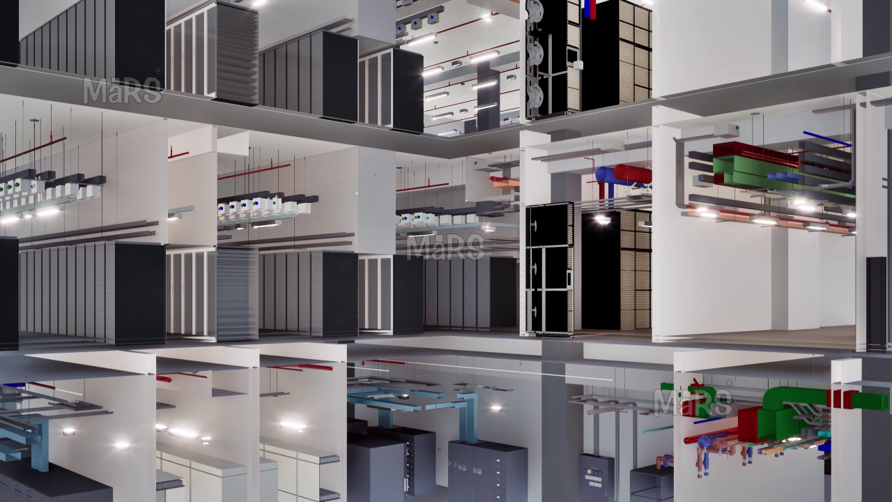
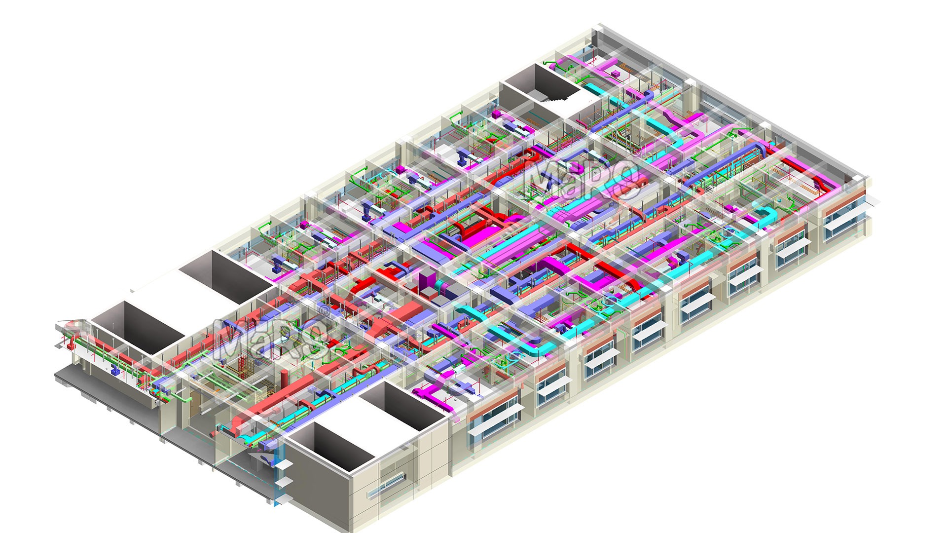
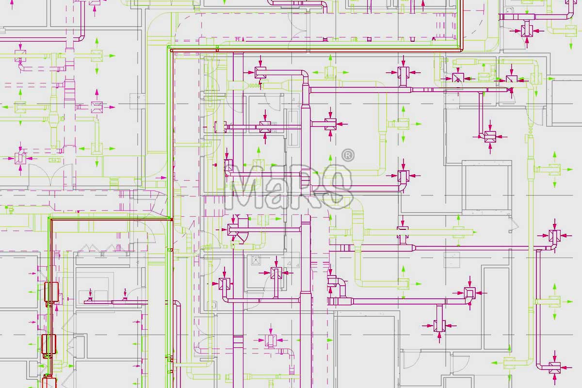
We assemble a single coordinated federated model combining all MEP disciplines and architectural/structural reference. This is the live document used throughout the coordination process.
Clash Detection Using Autodesk Navisworks
We run systematic Navisworks clash detection across all trade disciplines including hard clashes, clearance clashes, and workflow clashes using project-specific tolerances defined in the coordination protocol.
Clash Matrix Management
Every clash is catalogued, assigned, tracked, and resolved through a structured clash matrix. No issue falls through the cracks between coordination meetings.
RFI Support
When coordination uncovers design conflicts or specification gaps, we generate structured RFIs with clear markups and model references so your design team can respond accurately.
Shop Drawing Integration
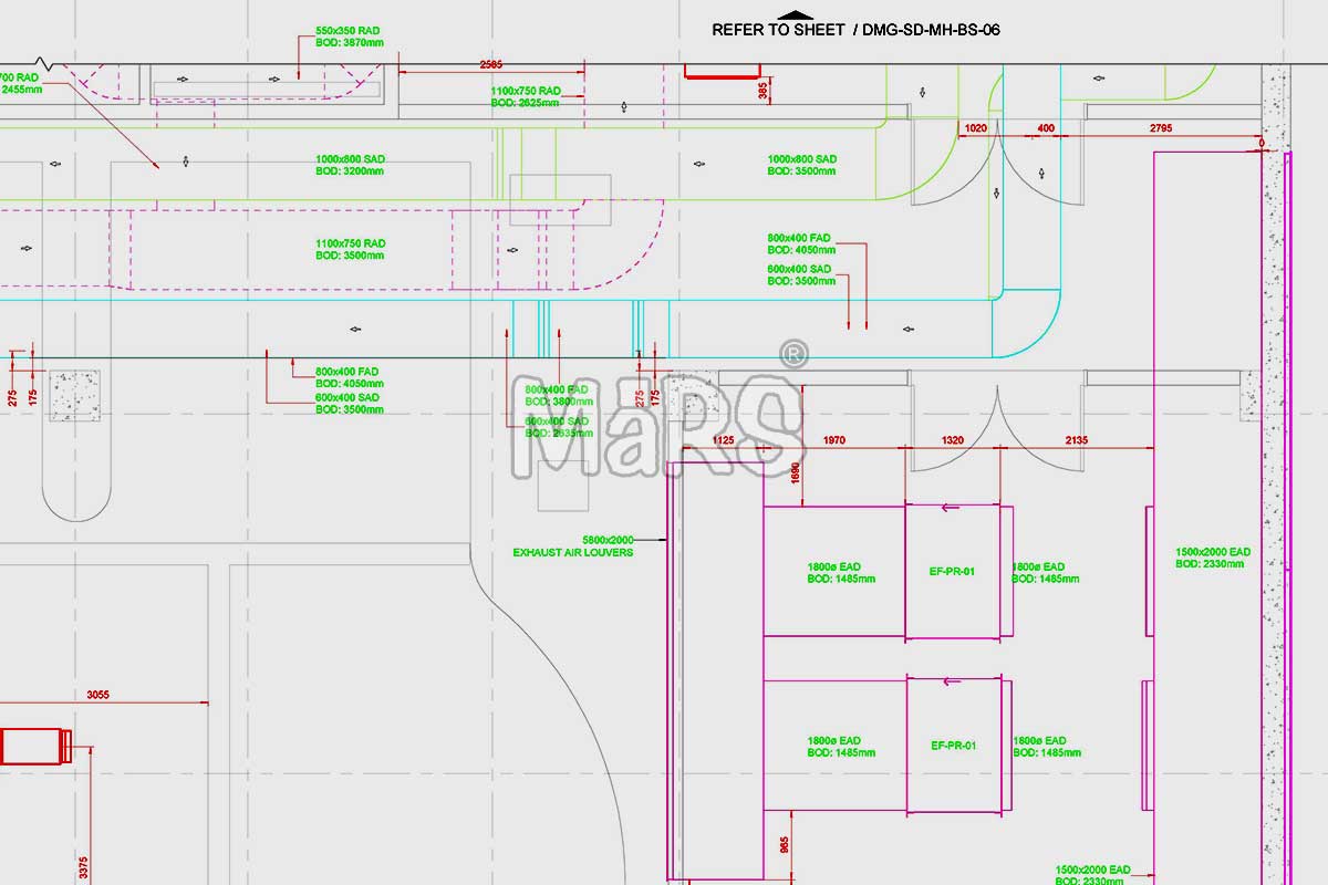
We incorporate contractor submittals and shop drawings directly into the coordination model, ensuring the installed system matches both the coordinated model and the fabricated components.
Spool and Fabrication-Level Detailing
For mechanical and plumbing scopes, we produce spool drawings and fabrication-ready details directly from the coordinated model.
What Each LOD Level Actually Delivers in MEP Coordination?
The term "LOD" is used inconsistently across the industry. Here is what each level means in the context of coordination deliverables, not just model geometry.
| LOD Level | What's Modeled | Coordination Purpose | Typical Contract Stage |
|---|---|---|---|
| LOD 200 | System layout, approximate sizes | Schematic routing only, not clash-valid | SD / early DD |
| LOD 300 | Exact geometry, routing, connections | Design-phase clash detection | DD / permit set |
| LOD 350 | Supports, hangers, sleeve locations, clearance zones | Construction-phase trade coordination | CD / pre-construction |
| LOD 400 | Fabrication dimensions, manufacturer data, spool geometry | Fabrication-ready model, shop drawing basis | Pre-fab / construction |
| LOD 500 | As-installed conditions, verified field dimensions | As-built record model for O&M | Post-construction |
Most coordination contracts specify LOD 350 as the deliverable standard for construction release. LOD 300 is insufficient for trade accountability. It does not include support structure or sleeve penetrations, which are the most common sources of field conflicts. If your current coordination scope does not specify LOD 350 minimum, it is worth reviewing before construction release.
Who We Support?
General Contractors
As the GC, you own the coordination schedule and the downstream consequences of unresolved clashes. Our MEP BIM coordination service gives you a single coordinated model you can hold all trades accountable to. We handle the coordination meetings, the clash matrix, and the construction release documentation — keeping your project moving and your subcontractors aligned.
Mechanical Contractors
Ductwork routing in congested ceiling spaces, equipment room layout, and sleeve coordination are your highest-risk coordination exposures. We model your scope to fabrication-ready LOD, resolve conflicts before your sheet metal is cut, and produce spool-level details your fabricators can work from directly.
Electrical Contractors
Conduit routing conflicts and clearance violations discovered in the field are expensive to fix and slow to resolve. We coordinate your electrical model against all other disciplines, validate NEC and code clearance requirements, and ensure your cable tray and conduit runs have a clear, unobstructed path before installation.
Plumbing & Fire Protection Contractors
Pipe routing, slope requirements, and sprinkler head placement create coordination constraints that compound across a building. We model your scope with proper slope, offset, and clearance built in — and coordinate sleeve locations and penetration details so your subs are not waiting on core drilling approvals in the field.
MEP Coordination by Project Type
Data Centres & Mission-Critical Facilities
Data centre coordination is categorically different from commercial construction. Cooling corridor routing must account for hot aisle/cold aisle containment geometry. Overhead cable tray density is typically 3–4 times higher than standard commercial. Power redundancy paths require dual routing logic that conflicts with architectural structure in ways standard clash detection rules do not flag automatically. ASHRAE A1–A4 thermal envelope requirements impose clearance constraints on CRAC/CRAH unit placement that must be resolved before ductwork routing begins.
We build data centre coordination models with N+1 and 2N redundancy logic incorporated from the first federated model. Cooling loop clash zones, busway routing through structural bays, and generator fuel line separation distances are coordinated as distinct rule sets. Not treated as generic MEP clearance problems.
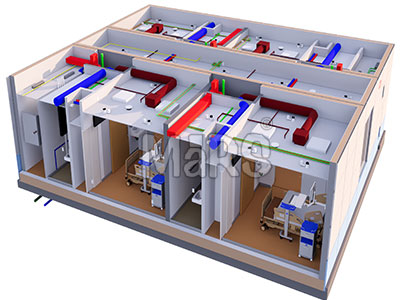
Healthcare Facilities
Hospital MEP coordination adds regulatory complexity that commercial coordination does not address. Medical gas systems require dedicated routing separation from electrical and plumbing under NFPA 99. HVAC pressure relationships between OR suites, sterile corridors, and adjacent spaces must be maintained to prevent cross-contamination. This means duct routing changes that look acceptable in a model may violate FGI infection control requirements in the field.
We coordinate healthcare projects against FGI Guidelines, NFPA 99, and ASHRAE 170 simultaneously. ICRA zone boundaries are modelled as coordination constraints. Medical gas coordination deliverables include zone valve location drawings and branch line separation documentation ready for AHJ submission.
Commercial Office Buildings
Commercial office coordination centres on congested ceiling plenums, multi-tenant electrical distribution, and HVAC zoning flexibility across leasable floors. The coordination challenge is not just resolving clashes — it’s sequencing mechanical, electrical, and plumbing routes so that future tenant demising can happen without cutting into coordinated infrastructure already installed.
We model commercial office projects with tenant zone boundaries as active coordination constraints. Electrical infrastructure is routed to support multiple future demising configurations. HVAC distribution is coordinated with future core drilling locations so the base building systems can be extended without disturbing the coordinated structure. For high-rise office towers, riser shafts and sleeve penetrations are coordinated floor-by-floor with structural clearances checked against the full building height, not just the individual floor plate.
Mixed-Use Developments
Mixed-use projects combine residential, retail, hotel, and office occupancies in a single structure — each with different MEP system requirements, code standards, and operating schedules. Coordinating these in a single federated model requires managing HVAC system separation (particularly where residential ventilation must be isolated from commercial kitchen exhaust), separate electrical metering infrastructure per occupancy type, and plumbing systems that serve radically different flow demand profiles on the same riser stack.
We build mixed-use coordination models with occupancy boundaries modeled as explicit constraint layers. Gas supply, domestic water, and fire suppression systems are coordinated separately per occupancy zone before the federated model is assembled, preventing the most common mixed-use conflict — a residential plumbing riser that interferes with the hotel’s mechanical room on the transfer level.
Retail & Shopping Centres
Retail MEP coordination is driven by tenant coordination requirements — each anchor tenant, food court operator, and inline retailer has their own MEP design standards and installation contractors. The base building coordination must establish infrastructure capable of serving the widest possible tenant mix, with capped stub-outs at each tenancy that can be extended without re-coordinating adjacent spaces.
We coordinate retail base building MEP to IBC and NFPA 13 requirements, model tenant demising walls as coordination references, and produce a landlord coordination package that documents exactly what each tenancy receives at handover — including electrical panel allocation, HVAC stub-out locations, plumbing connection points, and sprinkler branch line positions. This package becomes the reference document for each tenant’s own fit-out coordination.
Airports & Aviation Facilities
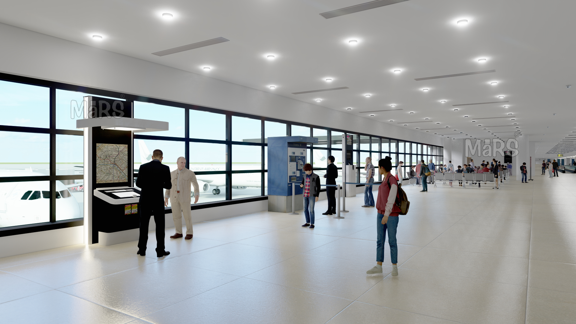
Airport MEP coordination operates at a scale and complexity level that exceeds most other building types. Passenger terminals have multiple occupancy zones with different pressurisation requirements, baggage handling areas with heavy mechanical plant, and security-sensitive electrical infrastructure that cannot share routing with non-secure systems. Concourse structures impose extreme coordination constraints — MEP routing must navigate between structural bays spanning 30+ metres while maintaining required clearances for maintenance access.
We coordinate airport projects against FAA advisory circulars for electrical and communication systems, ASHRAE 90.1 for terminal HVAC, and NFPA 130 where people-mover or transit connections are involved. We model baggage handling system envelopes as hard exclusion zones for MEP routing and coordinate HVAC pressure relationships between sterile and non-sterile zones. Critical system redundancy — dual power feeds, backup HVAC, and fire suppression staging — is modelled with full failover routing to ensure coordination reflects the actual installed redundancy logic.
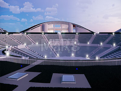
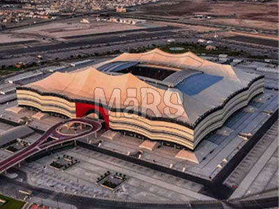
Stadiums & Sports Venues
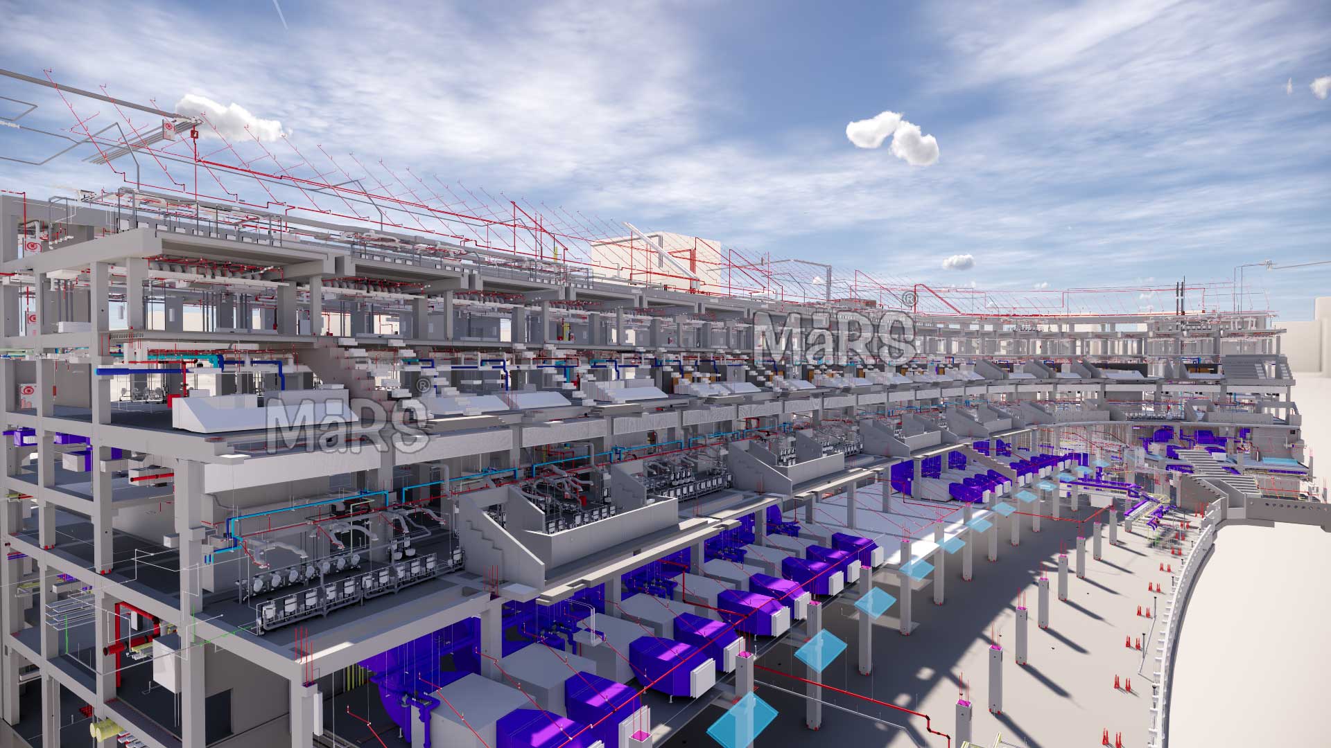
Stadium MEP coordination is characterised by massive plant rooms, long-span structural bays, and event-driven demand profiles that require systems sized for peak crowd loads with part-load efficiency during off-peak periods. Concourse MEP must be coordinated to serve dense occupancy in compact ceiling spaces while maintaining unobstructed sightlines and meeting egress code requirements.
We coordinate stadium MEP with event simulation logic — HVAC and electrical systems are coordinated not just for static layout but for the access, maintenance, and operational scenarios that occur during events, changeovers, and off-season maintenance. Pitch-level systems including field heating, drainage, and sports lighting power are coordinated separately from public concourse systems and then federated into the master coordination model. Broadcast and communications infrastructure, increasingly complex in modern stadiums, is coordinated as a sixth discipline alongside the standard MEPF trades.
Metro Stations & Transit Infrastructure
Metro station MEP coordination is among the most technically demanding environments we work in. Station ventilation must comply with NFPA 130 for smoke control and emergency ventilation, with duct runs navigating through structural tunnel connections, platform canopies, and mezzanine-level retail without compromising passenger sightlines or egress requirements. Traction power substations, third-rail systems, and signalling infrastructure impose rigid separation requirements from all other electrical systems.
We coordinate metro station MEP against NFPA 130, APTA rail safety standards, and local transit authority BIM requirements. Tunnel ventilation fan plant rooms, over-track exhaust systems, and emergency egress pressurisation are modelled as priority coordination elements before standard MEP routing begins. We work directly with transit authority BIM protocols including NBS BIM Object standards and any project-specific COBie data delivery requirements.
Government & Public Infrastructure
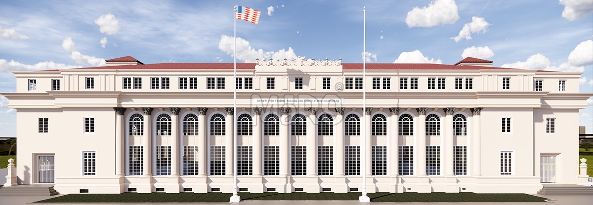
Government facilities — federal courthouses, military installations, public administration buildings, justice centres, and embassy complexes — carry specific coordination requirements that commercial projects do not. Security-sensitive electrical and communications infrastructure must be separated from general building systems with documented routing records. Force protection requirements impose structural constraints that affect MEP penetration locations. GSA, DoD, and State Department BIM standards require specific LOD deliverables, COBie data population, and model auditing protocols that standard commercial coordination workflows do not satisfy.
We have direct experience coordinating MEP for government projects against GSA BIM guidelines, UFC (Unified Facilities Criteria) standards, and project-specific security documentation requirements. Our coordination models are delivered with the full COBie data structure required for government asset management handover, and our clash resolution records are formatted for inclusion in project closeout documentation packages.
Educational Facilities
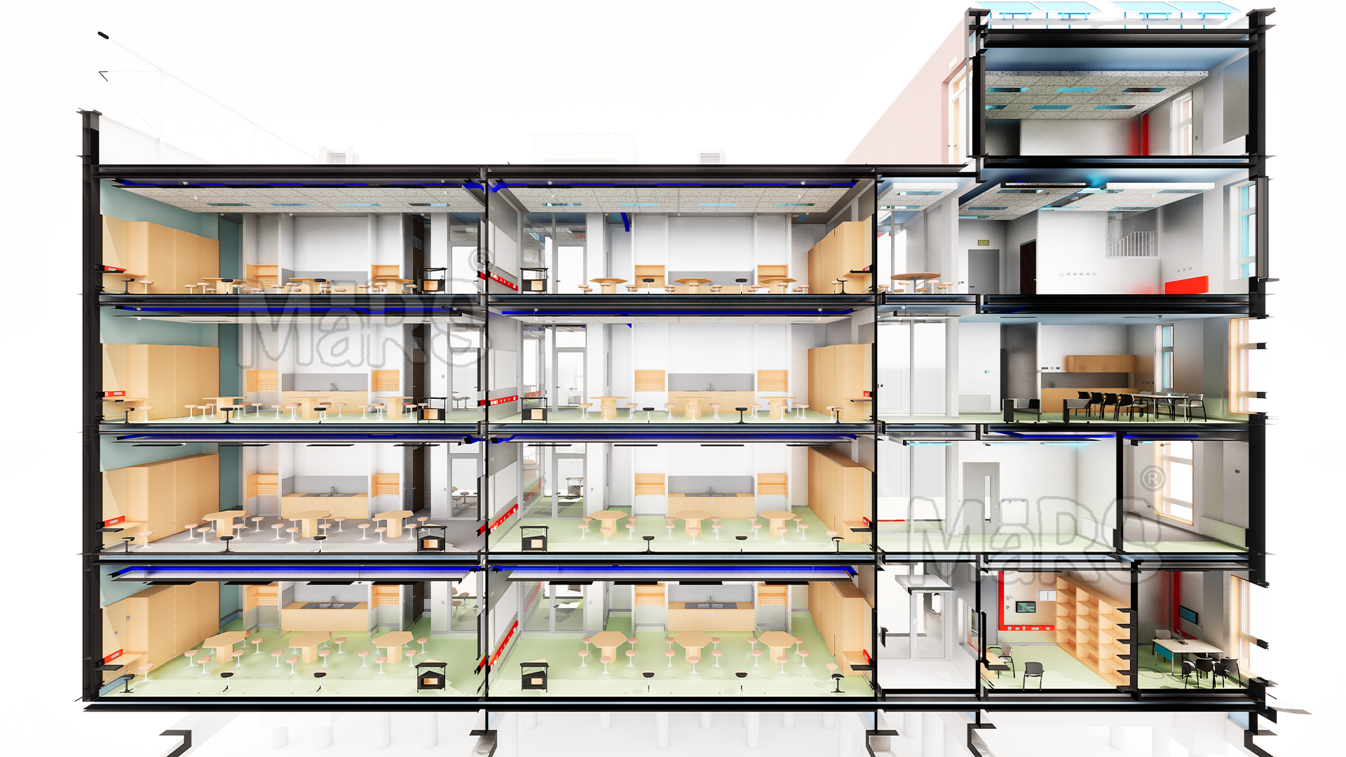
Schools, universities, and research campuses have MEP systems that combine high-occupancy HVAC loads, dense laboratory utilities, and complex audiovisual and IT infrastructure — all routed through corridor ceiling spaces designed to minimalist architectural standards. Phased construction of occupied campuses adds coordination complexity: new MEP infrastructure must be coordinated not just against the new structure but against live existing systems that remain in service throughout construction.
We coordinate educational facility MEP with phasing constraints built into the model from the start. Temporary system tie-in points and isolation sequences are documented as part of the coordination deliverable so the contractor can sequence work around occupied areas without redoing coordination each time a phase boundary changes.
Industrial & Manufacturing Facilities
Our MEP BIM Coordination Workflow
1. Model Intake and Standards Review
We receive all trade models and confirm file format, coordinate system, LOD requirements, and project BIM execution plan alignment before any work begins.
2. Model Validation and Cleanup
Each trade model is reviewed for geometry errors, missing elements, and inconsistencies that would compromise clash detection accuracy.
3. Initial Clash Test Runs
We run preliminary clash tests to identify the volume and priority of conflicts. High-density zones such as ceiling corridors, risers, and mechanical rooms are flagged first.
4. Clash Report Generation
Detailed clash reports are issued to each trade in a clear, actionable format with location, discipline, clash severity, and recommended resolution.
5. Weekly Coordination Meetings
We facilitate weekly coordination meetings with all trade representatives, working through the clash matrix in priority order and confirming design decisions in the model.
6. Issue Tracking
Every open clash is tracked to resolution. We do not close an issue until the model reflects the agreed solution and all affected trades have confirmed.
7. Sign-Off and Construction Release
Coordinated zones are formally signed off by the GC and trade leads, then issued for construction with a stamped coordination record.
Benefits of MEP BIM Coordination
- Detect and fix clashes between MEP systems and structures early
- Improve construction workflows for faster progress
- Provide accurate 3D BIM models for clear planning
- Enhance communication between teams for better collaboration
- Reduce costs by avoiding rework and material waste
- Speed up project completion with fewer delays
- Deliver precise and detailed construction documents
How MEP Coordination is scoped and priced?
MEP coordination is scoped based on four primary variables: gross square footage, ceiling plenum density, number of coordinated trades, and LOD requirement. The table below gives realistic benchmarks for US commercial and institutional projects.
| Project Type | Typical Size Range | Trades Coordinated | LOD Requirement | Typical Coordination Duration |
|---|---|---|---|---|
| Small commercial fit-out | Up to 30,000 SF | 3–4 trades | LOD 300–350 | 2–3 weeks |
| Mid-size commercial building | 30,000–150,000 SF | 4–5 trades | LOD 350 | 4–6 weeks |
| Large commercial / institutional | 150,000–500,000 SF | 5–6 trades | LOD 350–400 | 8–14 weeks |
| Data center / mission-critical | Any size | 5–6 trades + process | LOD 400 | 10–18 weeks |
| Healthcare facility | 50,000–300,000 SF | 6 trades incl. medical gas | LOD 400 | 10–16 weeks |
These durations assume weekly coordination meeting cadence, timely trade model submissions, and active design team participation in RFI responses. Projects with incomplete design documentation, late subcontractor model submissions, or active design changes during coordination will require schedule adjustments.
We do not charge by the clash count or by the round of revisions. Our scope is fixed to a coordinated construction release per zone. This means we stay on the project until each zone is signed off, not just until we have run one round of reports.
To receive a project-specific scope and fee estimate, submit your project documents and we will return a written scope of work within 48 hours.
Recognition That Reflects Coordination Quality
MaRS BIM Solutions is a recipient of the Big 5 Global Impact Award in Digital Twin Project of the Year and the Bentley Going Digital Award in Infrastructure. Both awards recognized projects where MEP coordination and BIM modeling directly contributed to measurable construction outcomes.
These are not design awards. They reflect execution accuracy, coordination quality, and the ability to deliver complex federated models that perform in the field. The same standard we apply to every MEP coordination engagement.


FAQs
We require Revit model files (or IFC exports) from each participating trade, the project BIM Execution Plan if available, design drawings in PDF or DWG format, and the project coordination schedule. We can work with partially developed models and will document what is missing during the validation phase.
MEP design produces the engineered system layouts such as duct sizes, pipe diameters, equipment specifications. MEP coordination takes those designs and resolves how all trades physically coexist in the building, including clash resolution, clearance verification, and sleeve coordination. Design tells you what to install; coordination tells you exactly where and how it fits.
Turnaround depends on project size and model complexity. For a 100,000 SF commercial floor plate, expect 4 to 6 weeks from model intake to coordinated construction release, assuming weekly meeting cadence and timely trade responses to clash reports.
Model ownership depends on your contract structure. In most US projects, the GC holds the federated coordination model and the individual trade subcontractors retain ownership of their discipline models. We document model ownership, access rights, and handover obligations in our BIM Execution Plan so there are no disputes after coordination is complete.
We recommend and facilitate weekly coordination meetings as the standard cadence. On fast-track projects or during high-conflict phases, we can increase to twice weekly. All meetings are documented with decision logs and updated clash status reports.
Design changes during coordination are handled through a formal change notice process. When issued design revisions affect coordinated zones, we assess the impact on the existing clash matrix, re-run affected areas, and issue an updated coordination record. We do not proceed on changed geometry without written confirmation of the revised design intent.
You receive a coordinated federated Revit model, final Navisworks file with all clashes resolved, coordination drawings by zone, a sleeve and penetration drawing package, a clash resolution log, and a signed construction release document for each coordinated zone.
Yes. We work natively in Autodesk Revit and Navisworks and can publish coordination models to Autodesk Construction Cloud or BIM 360. We support Procore for RFI and submittal workflows. We adapt to your project's defined BIM standards and data exchange protocols.
Yes. We regularly step into projects mid-construction where coordination was incomplete or stalled. We assess what has already been installed, update the model to reflect field conditions, and coordinate the remaining scope from that baseline forward.
We can build trade models in-house for mechanical, electrical, plumbing, or fire protection scopes where the subcontractor does not have Revit modeling capability. We work from shop drawings, design drawings, and equipment submittals to build a coordination-ready model.
Yes. Retrofit coordination starts with documenting existing conditions. Either through as-built drawings, scan-to-BIM from 3D laser scanning, or field measurement. We then coordinate new MEP scope against verified existing conditions, flagging conflicts between new systems and existing structure, equipment, and utilities that are remaining in place.
Get In Touch
Feel free to reach out to us for any inquiries or to discuss your project needs.