
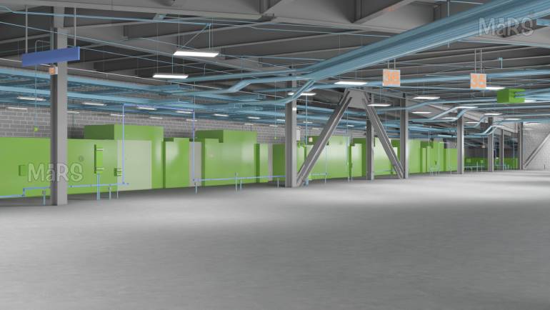
In large-scale commercial and industrial construction projects across the United States, poor coordination between electrical and MEP trades remains one of the leading causes of costly rework, schedule delays, and field conflicts. As buildings grow more complex, with dense mechanical rooms, layered ceiling plenum spaces, and tight routing corridors, the traditional approach of working from 2D drawings alone simply does not hold up.
BIM has fundamentally changed how trade contractors, general contractors, and project owners approach this challenge. By creating a single, shared 3D environment where every trade models and coordinates its systems simultaneously, BIM eliminates the ambiguity that fuels on-site disputes. This article explains how Electrical BIM Coordination and broader MEP Coordination workflows deliver measurable results, and what general contractors and trade contractors need to know to make BIM work on their projects.
Why Electrical and MEP Coordination Fails Without BIM?
Most coordination failures in US construction projects share a predictable root cause: each trade works from its own set of drawings, schedules its own rough-in work, and discovers conflicts only after materials are already installed. Electrical conduit runs into ductwork. Sprinkler mains block lighting fixtures. Structural beams eat into planned pipe routes.
The downstream costs are significant. The Construction Industry Institute has documented that rework on commercial projects can account for five to fifteen percent of total project costs. For a $50 million hospital or data center, that translates into millions of dollars in preventable waste.
Traditional coordination meetings, where each trade brings its own 2D drawings to the table and manually overlays them, cannot match the speed or accuracy required in today’s project environments. They are reactive by design. BIM, by contrast, makes coordination proactive.
What BIM Coordination Actually Looks Like for Electrical and MEP Trades?
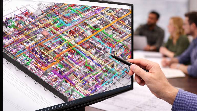
At its core, MEP BIM Coordination involves building each trade system as a fully detailed 3D model in software such as Autodesk Revit or Navisworks, then federating those models into a single combined file. Every duct run, conduit, cable tray, sprinkler line, pipe, and structural element occupies real space in a shared digital environment.
The Coordination Workflow
A well-run BIM coordination process on a US commercial project typically follows this sequence:
- Each MEP trade contractor builds its model to the agreed Level of Development (LOD), commonly LOD 300 or LOD 350 for coordination purposes
- Models are federated in a common data environment using software such as Autodesk Navisworks or BIM 360
- Clash Detection and Coordination runs are performed to identify hard clashes (physical intersections), soft clashes (clearance violations), and workflow conflicts
- Clash reports are distributed to responsible trades, who update their models and resubmit
- Coordination is signed off before fabrication or installation begins
For electrical contractors specifically, this means modeling conduit runs, cable trays, electrical panels, switchgear, transformers, and lighting layouts in full 3D, then coordinating that geometry against mechanical ductwork, plumbing mains, fire suppression headers, and structural framing.
Key Benefits of BIM for Electrical Contractors and MEP Subcontractors
Fewer Field Conflicts and Reduced Rework
When electrical conduit routes and cable tray layouts are modeled and coordinated before a single piece is installed, the number of field conflicts drops dramatically. BIM Clash Detection identifies intersections between electrical systems and other trades at the design stage, where resolving them costs far less than cutting and re-routing installed conduit.
Faster and More Accurate Prefabrication
Coordinated BIM models unlock a direct path to Prefabricated MEP Drawings. When the model is fully coordinated, electrical conduit assemblies, cable tray sections, and wiring harnesses can be dimensioned from the model and fabricated off-site with precision. Prefabricated assemblies fit correctly the first time because they were built from a model that already resolved all clashes.
This is particularly valuable on healthcare, data center, and higher education projects in the US, where tight timelines and phased occupancy make field installation efficiency critical.
Clearer Scope Boundaries and Reduced RFIs
One of the hidden costs in MEP coordination is the volume of Requests for Information (RFIs) generated by ambiguous drawings. When trades share a federated model, scope boundaries are visual and explicit. Electrical contractors can see exactly where their systems interface with mechanical or plumbing systems, reducing the guesswork that drives unnecessary RFIs and change orders. This is a key reason why BIM for General Contractors has become standard practice on complex projects.
Improved Installation Sequencing
BIM coordination also informs installation sequencing. By understanding the spatial relationships between all MEP trades in a given corridor or ceiling space, the general contractor can establish a logical installation order that prevents one trade from blocking another. 4D Scheduling tools attach construction timelines to model elements, so the GC and all subcontractors can visualize the installation sequence before work begins.
Electrical BIM Coordination Specifics Every Trade Contractor Should Understand
Electrical systems interact with virtually every other building system, which makes them one of the most coordination-intensive trades on any project. Understanding the common conflict zones helps electrical contractors and their BIM teams model more strategically.
Conduit Routing in Congested Ceiling Plenums
In office buildings, hospitals, and commercial facilities, ceiling plenum spaces are shared by electrical conduit, mechanical ductwork, plumbing mains, sprinkler headers, structural members, and data cabling. Without coordination, each trade claims the same space. BIM makes the competition for overhead routing space explicit and manageable. Electrical contractors should model conduit runs at the correct diameter, including fittings and boxes, and coordinate routing zones with the mechanical contractor early in the process.
Clearance Requirements Around Electrical Equipment
The National Electrical Code (NEC) requires specific working clearances around electrical panels, switchgear, and transformers. These clearances must be modeled, not just assumed. BIM allows the team to verify NEC clearances in 3D before equipment is placed, preventing situations where mechanical equipment or structural elements are installed too close to live electrical gear.
Cable Tray Coordination with Structural Elements
Cable trays run long distances through buildings and frequently interact with structural beams, columns, and framing. Coordinating cable tray routes with the structural model prevents field cuts and field-modified supports that add cost and time. MEP 3D Modeling at the correct LOD ensures these interactions are resolved before installation.
Why Electrical Contractors Need to Engage BIM Before Site Work Begins?
Some electrical subcontractors still approach BIM as something the GC manages, with their own involvement limited to submitting a basic model at project kickoff. This approach leaves significant value on the table.
Electrical contractors who actively participate in BIM Coordination from the start are better positioned to negotiate favorable routing zones, lock in installation sequences that match their manpower planning, and generate accurate material takeoffs from the coordinated model. They also reduce their exposure to back-charges for rework caused by unresolved clashes.
For trade contractors on complex projects, the argument for BIM is straightforward. BIM for Electrical Contractors is not simply a technology investment; it is a risk management strategy. Contractors who coordinate in BIM before site work begins face fewer surprises in the field, and surprises in construction are expensive.
From Coordinated Model to MEP Shop Drawings and Installation Packages
A coordinated BIM model is not just a coordination tool; it is the source of production deliverables. Once coordination is complete, the model can be used to generate MEP Shop Drawings and MEP Installation Drawings that reflect the fully coordinated design.
These drawings are dimensionally accurate because they originate from the 3D model. Field crews receive installation packages that show exact routing, elevations, and clearances, rather than interpreting underdeveloped 2D drawings in the field. This improves installation speed and accuracy, and reduces the volume of field decisions that lead to RFIs.
For projects with prefabrication components, the coordinated model also serves as the basis for HVAC Duct Shop Drawings and electrical conduit spool drawings that go directly to the fabrication shop. The result is a tighter connection between the design environment and the manufacturing process, reducing waste and improving quality.
BIM for Trade Contractors Across All MEP Disciplines
While electrical coordination is the focus of this article, the coordination benefits of BIM extend across all MEP disciplines. Mechanical, plumbing, fire suppression, and electrical contractors all work within the same federated model, which means improvements in one discipline’s coordination practices benefit the entire project team.
For general contractors managing multiple MEP subcontractors, a well-run BIM coordination process creates a shared source of truth that replaces the fragmented, trade-specific drawing sets that have historically caused so many field conflicts. The role of MEP BIM Coordination Services in modern construction has expanded significantly as project complexity has grown.
How General Contractors Use BIM to Manage Electrical and MEP Trade Coordination?

General contractors occupy a unique position in the BIM coordination process. They are responsible for establishing the coordination protocol, setting model requirements, running or overseeing clash detection, and ensuring that all trades meet their coordination obligations before work proceeds in the field.
Effective BIM for General Contractors means defining the BIM Execution Plan (BEP) at project kickoff. The BEP establishes model ownership, coordination milestones, software platforms, LOD requirements, and the clash detection schedule. Without a clearly defined BEP, coordination can stall as trades argue over whose model takes precedence.
On large projects, GCs often engage a dedicated BIM coordinator or work with a BIM services firm to manage the coordination process. This coordination manager runs the clash detection sessions, mediates trade conflicts, tracks issue resolution, and maintains the federated model as a record of the coordinated design.
Getting Started with BIM Coordination on Your Next Project
For contractors and project owners who are new to BIM coordination, the most important first step is establishing expectations early. BIM coordination requires investment in software, trained personnel, and time. These investments pay off through reduced rework, faster installation, and fewer disputes, but they require planning from project kickoff.
Key steps for getting coordination right include committing to a BIM Execution Plan that all trades sign on to, defining model LOD requirements appropriate to the project phase, setting a coordination schedule with regular clash detection milestones, and ensuring that all trade contractors have the BIM capability to participate meaningfully.
For teams that lack in-house BIM resources, working with a specialist BIM services provider who understands both the technical and coordination dimensions of the process can accelerate adoption and reduce the learning curve.
Conclusion
Electrical and MEP coordination challenges are not new to the US construction industry, but BIM provides the most effective tools currently available to address them. By modeling all trade systems in a shared 3D environment, running systematic clash detection, and generating coordinated installation packages before field work begins, project teams dramatically reduce rework, improve schedules, and protect their margins.
Whether you are a general contractor managing multiple trade contractors, an electrical subcontractor looking to reduce field conflicts, or a project owner trying to bring in a complex facility on time and on budget, investing in BIM coordination is one of the highest-return decisions available in today’s construction environment.