Construction sites often become coordination battlefields when building systems designed in isolation collide during installation. In dense utility zones, such as mechanical floors, riser shafts, and service corridors. Field teams frequently encounter misaligned penetrations, missing clearances, or last-minute re-routing because actual site conditions were not captured during design. These disruptions aren’t caused by poor modeling, but by the absence of verified spatial data at the preconstruction stage.
Trade contractors working on structural steel, HVAC, fire protection, and electrical systems depend heavily on early coordination. However, design models rarely account for field deviations, legacy structures, or tolerance zones, leading to hard clashes that go undetected until fabrication or installation. MEP Scan to BIM solutions help bridge this gap by capturing accurate site conditions, yet without them, rework, delayed inspections, and sometimes noncompliance with code-mandated clearances for fire dampers, electrical panels, or valve access become common. Relying solely on 2D markups or outdated as-builts puts even well-planned BIM coordination at risk.
Scan to BIM changes this by introducing detailed spatial verification at the front end of the coordination process. High-definition laser scans capture actual site geometry, which is then converted into intelligent BIM models aligned with project-specific LOD requirements. These models enable teams to validate design assumptions, run clash detection against existing conditions, and plan trade sequencing with confidence. This blog explores how AEC professionals can use Scan to BIM not just for documentation, but as a critical tool for reducing field risk, compressing schedules, and achieving real-world buildability.
What is Scan to BIM?
It is a construction-focused process that involves capturing existing site geometry through laser scanning and translating it into a structured, trade-ready BIM model used for design validation, spatial coordination, and construction planning. Unlike basic point cloud reference models, these outputs are intelligent and modeled with constructible detail, enabling real-time clash detection and trade integration. This process is valuable for retrofit-heavy environments, vertical extensions, or brownfield projects where legacy systems and undocumented changes often create coordination challenges.
Workflow Overview
- Site Laser Scanning: Use of terrestrial LiDAR or mobile laser scanners to capture architectural, structural, and MEP features with millimeter-level accuracy, even in inaccessible or congested areas.
- Point Cloud Registration and Processing: Alignment of multiple scan stations using survey control, noise filtering, and mesh optimization through tools like Autodesk Recap or Leica Cyclone.
- BIM Modeling in Revit or Similar Platforms: Model development by discipline with Level of Detail 300–400 targeting coordination requirements like service clearances, soffit tolerances, and riser alignment.
- Model Validation and Trade Preparation: Spatial verification against design intent, creation of views for trade-specific use, and alignment with project coordination zones.
Applications in AEC
- Reconfiguration of Existing Utility Rooms: Accurate modeling of mechanical spaces where pipe rerouting or equipment replacement is planned within tight footprints.
- Service Tie-Ins During Hospital or Data Center Expansions: Scanned data used to coordinate new MEP systems with uninterrupted facility operations.
- Basement-to-Roof Riser Coordination in High-Rise Construction: Prevents routing conflicts in congested shafts before trade installation begins.
- Urban Redevelopment with Partial Demolitions: Verifies geometry of retained structural elements and interfaces between new and existing construction.
- Infrastructure Projects with Unknown Subsurface Conditions: Captures geometry of utility tunnels, cable vaults, and manholes for integration into BIM before any excavation or structural work.
Why Use Scan to BIM for Clash Detection and Construction Planning
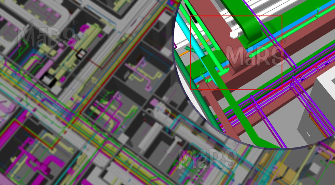
Field-level coordination failures often originate from overlooked conditions such as uneven slab edges, misaligned sleeve penetrations, or undocumented offsets in structural framing. These issues become critical when trade contractors begin routing duct mains, cable trays, or sprinkler branches in zones where tolerances are tight. It addresses this by capturing the built environment exactly as it exists, including structural deflections, previously installed conduits, or existing penetrations that were never documented. When BIM models reflect this verified geometry, clash detection becomes far more effective; exposing true conflicts between MEP systems and building structure before fabrication or site mobilization begins.
The impact goes beyond spatial conflict resolution. Teams managing prefabrication, hoisting logistics, and phased access planning can link point-verified models with project timelines and site constraints to simulate exact installation paths. For example, routing large AHUs through a mechanical floor with limited crane reach or sequencing MEP trades inside a congested riser shaft becomes possible only when models reflect millimeter-accurate site conditions. This level of confidence is critical in hospital retrofits, manufacturing plant shutdowns, and mixed-use high-rises where construction tolerances are low and downtime is not an option.
Pro Tip: Instead of scanning entire floors uniformly, focus high-resolution scanning efforts on critical clash zones like slab edge transitions, hanger-loaded soffits, and areas with early core wall pours. These zones often contain the highest volume of undocumented shifts and are where most multi-trade rework originates during installation.
Understanding Clashes in AEC Projects
Clashes in AEC construction emerge when design intent does not align with spatial reality, particularly in multi-trade integration zones such as service shafts, mechanical floors, and overhead corridors. These conflicts often involve duct mains cutting through transfer beams, electrical conduits running across fire-rated partitions, or sprinkler heads colliding with lighting layouts due to inconsistent model references. Clashes are not limited to geometry; they reflect process gaps, missing field data, and lack of shared coordination logic. Without early clash identification based on verified conditions, contractors face field stoppages, trade stacking, and out-of-sequence work, directly affecting cost, safety, and schedule.
What Causes Clashes?
- Trade models developed in silos without field-verified context
- Inconsistent use of coordination zones or shaft allocation logic
- Use of generic families lacking true clearance parameters
- Unaligned datum points or origin mismanagement across models
- Existing site deviations not reflected in design assumptions
- Compressed design timelines forcing incomplete coordination sign-offs
Traditional vs. BIM-Enabled Clash Detection
| Aspect | Traditional Method | BIM-Enabled Method |
| Data Source | As-built drawings, site walks, redlines | High-density laser scans, point cloud-based models |
| Clash Detection Approach | Manual overlays on 2D sections, tape measurements | Rule-based, multi-discipline model checks using Navisworks or Solibri |
| Accuracy Level | Prone to site deviations, relies on assumptions | Reflects true site geometry and tolerances from scan data |
| Responsiveness | Reactive, issues arise during installation | Proactive, clashes flagged before material release or fabrication |
| Resolution Workflow | Requires field improvisation or redesign | Model-based resolution through structured BIM coordination workflows |
| Impact on Project Schedule | Causes downstream trade delays, rework, and inspection failures | Enables clean sequencing, prefabrication readiness, and risk mitigation |
| Collaboration and Visibility | Limited to site supervisors and paper trails | Real-time access for all stakeholders via cloud platforms and issue logs |
Types of Clashes in BIM Coordination
Hard Clashes
These occur when two modeled components physically intersect within the same spatial zone, often resulting in immediate field conflict. Examples include fire sprinkler mains colliding with post-tensioned beams in basement ceilings, or chilled water pipes intersecting concrete cores due to incorrect sleeve placement. Such clashes are critical in fast-paced builds where structural and MEP systems install in parallel.
Soft Clashes
These involve violations of operational or regulatory clearances rather than direct physical contact. For example, VRF units placed against partition walls without access for maintenance, or breaker panels modeled within 800mm of obstruction, breaching NEC code requirements. These are typically missed in coordination unless specific clearance rules are applied during conflicts.
4D Workflow Clashes
Sequencing-related conflicts that arise when construction logic is not aligned across trades. A common case is installing drywall before finalizing behind-wall piping, leading to rework. Another scenario involves scaffold removal scheduled before overhead duct installation in atrium zones, causing unsafe or inaccessible work conditions.
5D Data Clashes
These stem from discrepancies in model-linked cost or procurement data. For instance, embedded sleeves shown as PVC in the BIM model but ordered as HDPE, or quantity mismatches where modeled conduit lengths differ from BOQ export, causing material delays or incorrect pricing. These clashes typically surface late unless BIM and estimating tools are integrated.
Scan to BIM Workflow for Clash-Free Construction Planning
Step 1: Scope Setup
Identify trade zones, scanning limits, and target LOD for coordination.
Step 2: Site Scanning
Capture built conditions using LiDAR in shafts, ceilings, and core zones.
Step 3: Cloud Alignment
Register scans to project coordinates and remove noise from high-traffic areas.
Step 4: Trade Modeling
Extract walls, slabs, ducts, and pipes into discipline-specific Revit models.
Step 5: Clash Testing
Run multi-trade clash rules in Navisworks or Solibri for real-site fit.
Step 6: Issue Resolution
Log clashes, assign to trades, and close via coordination review cycles.
Step 7: Build Simulation
Connect model with timeline and cost to simulate phasing and access.
Benefits of Scan to BIM for Clash Detection
- Captures true-to-site geometry for trade-specific modeling without manual measurements.
- Flags system clashes in risers, corridors, and ceiling zones before mobilization.
- Prevents costly rework during duct drop, cable tray, or pipe sleeve installation.
- Supports zone-based sequencing to avoid trade stacking and site congestion.
- Enables accurate prefab layout for multi-service racks and vertical modules.
- Reduces downtime by resolving layout issues before material delivery.
- Improves design-trade communication using federated, issue-tagged models.
- Confirms access zones for maintenance, safety, and code compliance.
Best Practices for AEC Teams
- Define riser, shaft, and corridor ownership before modeling to avoid scope overlaps.
- Align scan station setup with BIM coordination zones to reduce rework in dense areas.
- Use clash rule sets customized per trade like duct-to-beam at 100mm tolerance, cable tray to sprinkler at 75mm.
- Freeze existing condition models after QA to prevent scan drift in downstream trades.
- Prioritize high-risk areas such as plant rooms, and switchgear zones for early clash resolution.
- Tag clashes by location and system type to streamline trade-specific issue routing.
- Track access clearances and valve zones during coordination, not post-installation.
- Assign lead coordinators by floor or system like HVAC, FP, electrical for faster sign-offs.
- Schedule coordination around construction-critical zones, not drawing deadlines.
- Archive resolved clash snapshots for inspection teams and handover documentation.
Outsourcing Scan to BIM Services
Many construction teams lack the bandwidth or internal capability to manage high-accuracy scan-to-model workflows alongside daily coordination tasks. Outsourcing to a BIM specialist ensures that point cloud data is processed with survey-grade alignment, scope-specific modeling, and clash-ready geometry tuned to project LOD requirements. This becomes essential when existing conditions must be modeled to LOD 350+ within compressed preconstruction windows such as when riser shaft models are needed for sleeve box-outs, or when a plant room must be clash-tested before steel delivery. External teams can also provide multi-discipline model integration, reducing the need for internal rework across trades.
General contractors benefit by offloading scope-heavy areas like mechanical floors or structural retrofit zones where in-house BIM teams may struggle with detail or accuracy. MEP coordinators use outsourced services to receive discipline-specific models that match prefabrication logic and system clearances. BIM consultants overseeing multi-package delivery use third-party providers to avoid bottlenecks during early clash runs. Facility managers in healthcare or manufacturing, gain clean as-built digital records that meet compliance needs without disrupting ongoing operations. For fast-track, retrofit, or shutdown-driven projects, outsourcing enables high-detail modeling without overloading the core team.
Conclusion
Using Scan to BIM shifts construction coordination from guesswork to precision by delivering verified geometry for risers, core walls, ceiling systems, and shaft routing before a single hanger is drilled or duct is fabricated. Instead of resolving clashes mid-installation or issuing last-minute RFIs on congested floors, teams gain the ability to sequence trades with confidence, prefabricate with accurate offsets, and lock in clearances based on actual site constraints. Whether planning core cut-outs for existing slabs or routing services around live systems, early integration of Scan to BIM transforms coordination into a proactive, model-driven process that protects timelines, budgets, and buildability from day one.