For electrical contractors, general contractors, and MEP coordinators working on large commercial, healthcare, or mixed-use projects in the United States, routing electrical conduit through a complex building is rarely straightforward. Structural steel, HVAC ductwork, plumbing lines, fire suppression systems, and architectural elements all compete for the same ceiling and wall space. Without a structured coordination process, the result is costly field conflicts, rework, and project delays.
Building Information Modeling (BIM) has become the construction industry’s most effective answer to this challenge. When implemented correctly, BIM-based Electrical Conduit Routing enables teams to plan, route, and install electrical conduit systems with precision before a single worker steps onto the job site. This article breaks down how BIM streamlines conduit routing in complex buildings and why it is quickly becoming a baseline expectation on competitive projects across the country.
Why Conduit Routing in Complex Buildings Is a Coordination Problem?
Conduit routing sounds like a simple task on paper: run pipe from panel to device, follow the shortest path, and avoid obstructions. In practice, the coordination required on a multi-story hospital, data center, or high-rise office building is far more demanding.
Electrical conduit runs in three dimensions through spaces that are also occupied by mechanical ductwork, structural beams, sprinkler mains, communication cabling, and low-voltage raceways. Traditional 2D drawings cannot capture these spatial relationships accurately. Contractors working from flat plans regularly encounter conditions in the field that do not match the drawings, leading to change orders, schedule impacts, and conflict resolution meetings that eat into margins.
According to Autodesk, construction teams that use BIM for electrical coordination report significantly fewer design conflicts and reduced rework on complex projects. The 3D model becomes the single source of truth for all trades, replacing guesswork with geometry.
Electrical Conduit Types and Why Routing Decisions Matter
Not all conduit is the same, and the type of conduit specified for a project directly affects how routing decisions are made and modeled in BIM. Understanding the characteristics of each conduit type is essential for electrical teams planning runs in complex buildings.
Rigid Metal Conduit (RMC) and Intermediate Metal Conduit (IMC)
Rigid Metal Conduit and Intermediate Metal Conduit are the heaviest-duty options used in commercial and industrial construction. Both are made from steel and provide maximum protection for conductors in areas subject to physical damage, outdoor exposure, or harsh industrial environments. RMC and IMC require threaded fittings and are more labor-intensive to install because bending is done with mechanical or hydraulic benders and every change in direction requires precision.
In BIM, RMC and IMC runs must be modeled with accurate bend radii and precise offsets. Because these conduits cannot be field-adjusted as easily as flexible alternatives, the routing path approved in the model needs to be manufacturable and installable exactly as drawn. Any discrepancy between the model and field conditions becomes a significant rework event.
Electrical Metallic Tubing (EMT)
Electrical Metallic Tubing is the most widely used conduit type in commercial construction in the United States. EMT is lightweight, thin-walled, and uses compression or set-screw fittings rather than threads. It can be bent on-site with a hand bender for smaller sizes or a mechanical bender for larger diameters.
EMT is the primary conduit type modeled in BIM coordination for above-ceiling branch circuit and feeder runs in office buildings, healthcare facilities, and retail spaces. BIM models for EMT typically account for 90-degree elbows, offsets, kick-outs, and saddle bends. When conduit runs are modeled accurately in BIM, that data can be exported directly to fabrication equipment, allowing shop-bent EMT sections to be prefabricated and delivered to the floor for direct installation.
Flexible Metal Conduit (FMC) and Liquid-Tight Flexible Conduit (LFMC)
Flexible Metal Conduit and Liquid-Tight Flexible Metal Conduit are used for final connections to equipment that vibrates, such as motors, HVAC units, and transformers, or in locations where rigid routing is impractical. FMC and LFMC are typically the last segment of a conduit run and are modeled in BIM as whips or equipment connections rather than as routed runs.
In healthcare and data center projects where equipment is on vibration isolation pads or requires seismic flexibility, LFMC connection lengths are specified in the BIM model to ensure code compliance and coordination with equipment rough-in locations.
PVC Conduit and HDPE
Schedule 40 and Schedule 80 PVC conduit is used underground, in concrete encasements, and in corrosive environments. HDPE conduit is increasingly specified for direct-buried site utility runs and telecommunications infrastructure. In BIM, underground conduit routing is coordinated with civil, plumbing, and telecommunications models to resolve conflicts below grade, where excavation and remediation are expensive.
Modeling underground conduit banks in BIM allows teams to visualize crossing conflicts with storm drain, sanitary sewer, domestic water, and gas lines before the trench is open.
Conduit Routing Challenges by Building Type
The specific challenges of conduit routing vary significantly by building type. BIM coordination strategies must be tailored to the physical and operational characteristics of the facility being built.
Healthcare Facilities
Hospitals and medical office buildings are among the most demanding environments for electrical conduit coordination. Patient care areas require dedicated circuit home runs that cannot share conduit with other branch circuits. Operating rooms, imaging suites, and ICUs have stringent requirements for isolated power systems, emergency power panels, and redundant circuits that multiply the number of conduit runs in already-congested ceiling spaces.
Healthcare projects also involve significant coordination with medical gas piping, nurse call systems, low-voltage systems, and building automation. In a typical hospital corridor ceiling, it is not unusual to see 20 or more separate systems competing for the same 18-inch deep plenum. BIM is not optional on these projects. Without a coordinated model, the ceiling installation becomes a daily problem-solving exercise that delays every trade.
The National Electrical Code (NEC), particularly Articles 517 and 700, governs electrical installations in healthcare occupancies and emergency systems. BIM for healthcare projects must reflect code-compliant circuit separation, grounding requirements, and equipment clearances. Electrical contractors working in healthcare environments can benefit significantly from structured BIM services that are purpose-built for high-density coordination environments.
Data Centers
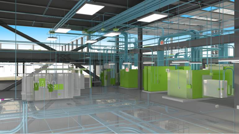
Data centers present a different kind of routing complexity. The density of power distribution, structured cabling, bus duct, and cooling infrastructure in a modern hyperscale or colocation facility is extreme. Power conduit must be routed to maintain clear separation between redundant power paths (Path A and Path B), which are typically color-coded in the BIM model for visual clarity during coordination.
Raised floor environments add a second routing dimension below the slab, where power whips, copper ground grids, and communication infrastructure are routed in coordination with perimeter cooling unit connections. Overhead cable trays, ladder rack, and conduit runs for emergency generator feeders, PDU outputs, and UPS systems must be modeled and coordinated above the data hall ceiling to maintain clearances for airflow management.
BIM for Data Centers brings measurable value to the projects by centralizing coordination across all critical systems. The model allows power, cooling, and structured cabling teams to work within a shared environment, catching conflicts early and reducing on-site delays. Redundant power paths, cooling unit connections, and overhead cable management can all be visualized and validated before installation. Once the facility is operational, the BIM model serves as a living asset record. This supports capacity planning, maintenance workflows, and future infrastructure expansions with accurate, spatially referenced data.
High-Rise Commercial and Mixed-Use Buildings
High-rise office towers and mixed-use buildings introduce vertical coordination as a primary challenge. Electrical risers, which carry feeders from the main switchgear room to electrical closets on each floor, must be coordinated with mechanical shafts, elevator hoistways, plumbing stacks, and structural core elements. In tall buildings, misaligning a riser sleeve by even a few inches between floors compounds into a significant offset by the time the error is discovered.
BIM models for high-rise projects allow teams to verify riser alignment floor-by-floor before any core drilling or sleeve installation takes place. Structural engineers can review the model to confirm that sleeve locations do not compromise slab or shear wall integrity.
Industrial and Manufacturing Facilities
Industrial buildings often have large, open floor plates with overhead cranes, process piping, and heavy-duty electrical distribution that must be coordinated with structural support systems. In these environments, conduit is frequently run in cable tray or on unistrut support systems hanging from the structure. The routing of motor control circuits, variable frequency drive conduit, and instrumentation wiring adds another layer of coordination complexity.
BIM for industrial projects also supports coordination with process mechanical and instrumentation systems, which are typically handled by separate engineering disciplines. Integrating these models into the federated BIM file ensures that electrical conduit routes do not conflict with process piping, equipment maintenance access zones, or overhead crane travel paths. Mechanical contractors working on these same projects rely on coordinated BIM workflows to protect their system routing.
NEC Code Requirements That Directly Affect Conduit Routing Decisions
Conduit routing in BIM is not just about avoiding physical conflicts. The National Electrical Code establishes specific requirements that shape where and how conduit can be routed. Modeling these requirements into the BIM workflow ensures that the coordinated installation is also a code-compliant installation.
Bend Limitations and Pull Points
NEC Section 358.26 (for EMT) and related articles for other conduit types limit the total number of bends between pull points to 360 degrees. In a complex routing path, this means that every time a conduit changes direction to avoid a structural member, a duct, or another conduit, that bend is counted against the allowed total. BIM allows designers and coordinators to track cumulative bends in a run and flag routes that approach the limit, ensuring that pull boxes or junction boxes are placed correctly before installation.
Without BIM, electricians in the field sometimes discover mid-installation that a routed path has too many bends to pull wire through. Adding a pull box after conduit is already installed in a tight ceiling space is costly and time-consuming.
Conduit Fill Requirements
NEC Chapter 9 tables govern how many conductors can be pulled through a given conduit size, based on conductor size and insulation type. When designing a conduit routing path, the conduit size must be selected based on the number and size of conductors it will carry. In BIM, conduit is modeled at its actual specified size, and that size affects how it fits within a coordinated ceiling section.
BIM-linked electrical design tools can associate conductor schedules with modeled conduit, allowing teams to verify that the routed conduit size is correct for the planned circuit loading and to flag any undersized runs before installation.
Clearance from Other Systems
NEC and NFPA standards require specific clearances between electrical conduit and certain other building systems. Electrical conduit must maintain separation from hot surfaces such as steam piping and HVAC exhaust flues. Certain sensitive circuits require physical separation from electromagnetic interference sources. In healthcare occupancies, isolated ground circuits must maintain separation from standard circuits.
BIM soft clash detection is the most effective tool for enforcing these clearance requirements systematically. Soft clash rules can be configured in Navisworks or similar platforms to flag any conduit that is within a specified distance of a non-compliant adjacent system, generating a report that coordination teams can address before construction.
Conduit Support, Hanger Coordination, and Structural Integration
Routing the conduit is only part of the coordination challenge. Every conduit run must also be supported. The NEC specifies maximum support intervals for each conduit type, typically every 10 feet for EMT and more frequently near fittings and boxes. In a complex building with dozens of parallel conduit runs, the number of required support points is significant.
BIM-based conduit coordination enables teams to plan unistrut trapeze assemblies, threaded rod hanger locations, and beam clamp positions as part of the model. When hanger locations are coordinated with the structural model, teams can confirm that attachment points land on accessible structural elements rather than on non-structural decking or in conflict with other trade supports.
On projects where multiple trades use shared trapeze assemblies to maximize ceiling clearance, BIM is essential for designing those assemblies accurately. A coordinated trapeze that carries electrical conduit, communication pathways, and sprinkler branch lines must be designed with the correct member sizes and attachment details. Modeling these assemblies in BIM ensures that every trade’s system fits on the trapeze and that the structural load is appropriate for the hanger point.
Coordination Insight:
On healthcare and data center projects, consolidating shared hanger support systems in BIM can reduce the number of individual attachments to the structure by 30 to 50 percent, freeing up structural capacity and reducing installation time for all trades.
Seismic Bracing Considerations for Electrical Conduit Systems
In seismic design categories C through F, which cover much of California, the Pacific Northwest, parts of the Mountain West, and areas of the Midwest and South, electrical conduit systems must be seismically braced. NFPA 13 and IBC Chapter 16 establish bracing requirements for conduit and cable tray systems based on system weight, size, and height above the floor.
Seismic bracing adds another coordination layer to conduit routing. Lateral braces and longitudinal braces must attach to the structure at locations that are strong enough to resist the calculated seismic loads. Bracing locations must be coordinated with the structural model to confirm that suitable attachment points exist along the conduit route.
BIM allows seismic bracing to be designed and modeled as part of the coordinated electrical model, so that brace locations, attachment hardware, and clearance zones are visible to all trades during coordination. This prevents a common field condition where one trade’s seismic brace conflicts with another trade’s pipe or duct in an already-crowded ceiling zone.
How BIM Supports Electrical Conduit Routing?
Building a Federated 3D Model
The foundation of BIM-based coordination is a federated model. Each discipline, including structural, architectural, mechanical, plumbing, and electrical, builds its own model in software such as Autodesk Revit or Trimble MEP. These individual models are then combined into a single coordinated file using a clash detection platform such as Autodesk Navisworks or BIM 360.
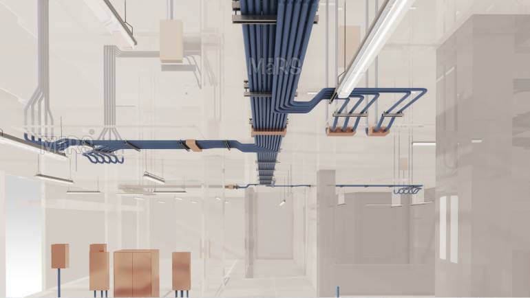
For electrical teams, this means modeling every conduit run in three dimensions, including size, material, routing path, supports, and connection points. Power conduit, fire alarm raceways, data and communication runs, and lighting branch circuits are all represented in the model at their actual proposed locations.
This level of detail allows all project stakeholders to see exactly where conduit will travel through the building before installation begins. Conflicts with mechanical ducts, structure, or other systems are identified and resolved in the model rather than in the field.
Clash Detection and Resolution
Clash detection is one of the most direct benefits of BIM coordination for electrical teams. Autodesk Navisworks and similar platforms generate automated clash reports that identify hard clashes (physical overlaps between two elements), soft clashes (elements that violate clearance requirements), and workflow clashes (scheduling conflicts between trades).
A common example in electrical coordination is a power conduit routed through the same ceiling zone as a large HVAC supply duct. Without BIM, this conflict is discovered by an electrician on a lift in the field. With BIM, the clash is flagged in the coordination software before installation, and the team agrees on a revised path during a BIM coordination meeting.
Resolving clashes in the model is exponentially less expensive than resolving them in the field. Studies from the Construction Industry Institute estimate that the cost of rework during construction averages 5 percent of total project cost. BIM coordination directly reduces that number.
Optimizing Routing Paths with BIM Tools
Beyond conflict avoidance, BIM enables electrical teams to actively optimize conduit routing paths. Design engineers and electricians can test multiple routing scenarios in the model and evaluate them based on material quantities, labor hours, code compliance, and accessibility for future maintenance.
BIM software tools can also generate conduit quantities directly from the model. Rather than manually scaling quantities from 2D drawings, project managers can extract accurate material takeoffs from the coordinated model, reducing procurement errors and improving cost certainty.
Conduit Routing Precision and Shop Prefabrication
One of the most significant downstream benefits of accurate conduit routing in BIM is the ability to prefabricate conduit assemblies in a controlled shop environment. When conduit routing paths are modeled to LOD 350 or higher, the 3D geometry of every run, including bend angles, offset dimensions, and cut lengths, can be exported directly to conduit fabrication software such as Trimble or Condumax.
Shop fabrication removes field bending and cutting from the critical path. Electricians on the job site receive pre-bent, labeled conduit sections that install directly into the coordinated position without field measurement. The result is faster installation, less material waste, and a more consistent finished product.
Prefabrication is particularly valuable on repetitive floor plates, such as those found in high-rise office buildings and multi-family residential towers, where the same conduit layout repeats on every floor. A single coordinated and prefabricated assembly package can be replicated across dozens of floors, reducing labor hours and ensuring uniformity throughout the building.
Key Advantage:
Electrical contractors who complete electrical modeling and coordination before site work begins can hand off fabrication-ready conduit data to their shop weeks ahead of the installation phase, compressing the project schedule without increasing field labor costs.
Above-Ceiling Zone Management for Electrical Conduit
In most commercial buildings, the ceiling plenum is the most contested coordination zone on the project. Mechanical, plumbing, fire protection, electrical, and low-voltage systems all compete for vertical space between the structural deck and the finished ceiling height. Managing this zone effectively requires more than avoiding clashes. It requires a deliberate strategy for assigning vertical space to each system before modeling begins. The BIM Forum Level of Development Specification provides the modeling standards that enable this kind of structured, multi-trade elevation coordination across all disciplines on a project.
Trade Stacking and Elevation Zoning
BIM coordination teams on complex projects typically establish a trade stacking order and elevation zone map before individual trade models are developed. This coordination strategy assigns a primary elevation range to each system type: structural and mechanical at the highest elevation, sprinkler mains below that, electrical feeders and communication cable tray in the mid-zone, and branch circuit conduit and low-voltage wiring in the lowest zone just above the ceiling grid.
Electrical teams working within this framework model their conduit runs to stay within their assigned elevation zone wherever possible. When a run must cross into another zone to reach a panel or device, that crossing is flagged as a coordination item and resolved collaboratively with the affected trades.
Maintaining Maintenance Access Clearances
Beyond installation clearances, conduit routing must account for future maintenance access. NEC Article 110 establishes working space requirements around electrical equipment, and these clearances must be maintained not just at panels and switchgear but also at pull boxes and junction boxes distributed throughout the conduit system.
BIM models can be configured to display maintenance access zones as transparent geometric volumes around electrical equipment. Any conduit routed through these volumes is flagged as a soft clash, prompting the team to reroute to maintain future access without obstructing other systems.
This practice is especially important in mechanical rooms, electrical rooms, and telecommunications closets where multiple systems converge and maintenance access must be preserved for the life of the building.
Conduit Routing for Critical Power and Emergency Systems
Critical power systems, including emergency generator feeders, uninterruptible power supply (UPS) circuits, and essential branch circuits in healthcare occupancies, carry specific routing requirements that go beyond standard coordination.
Physical Separation of Normal and Emergency Power
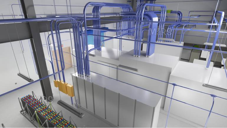
NEC Article 700 requires that emergency system wiring be kept entirely independent of other wiring from the point of entry of the supply conductors to the load. This means emergency conduit runs cannot share raceways, enclosures, or junction boxes with normal power circuits. In a complex building, maintaining this physical separation throughout the full routing path requires deliberate BIM coordination.
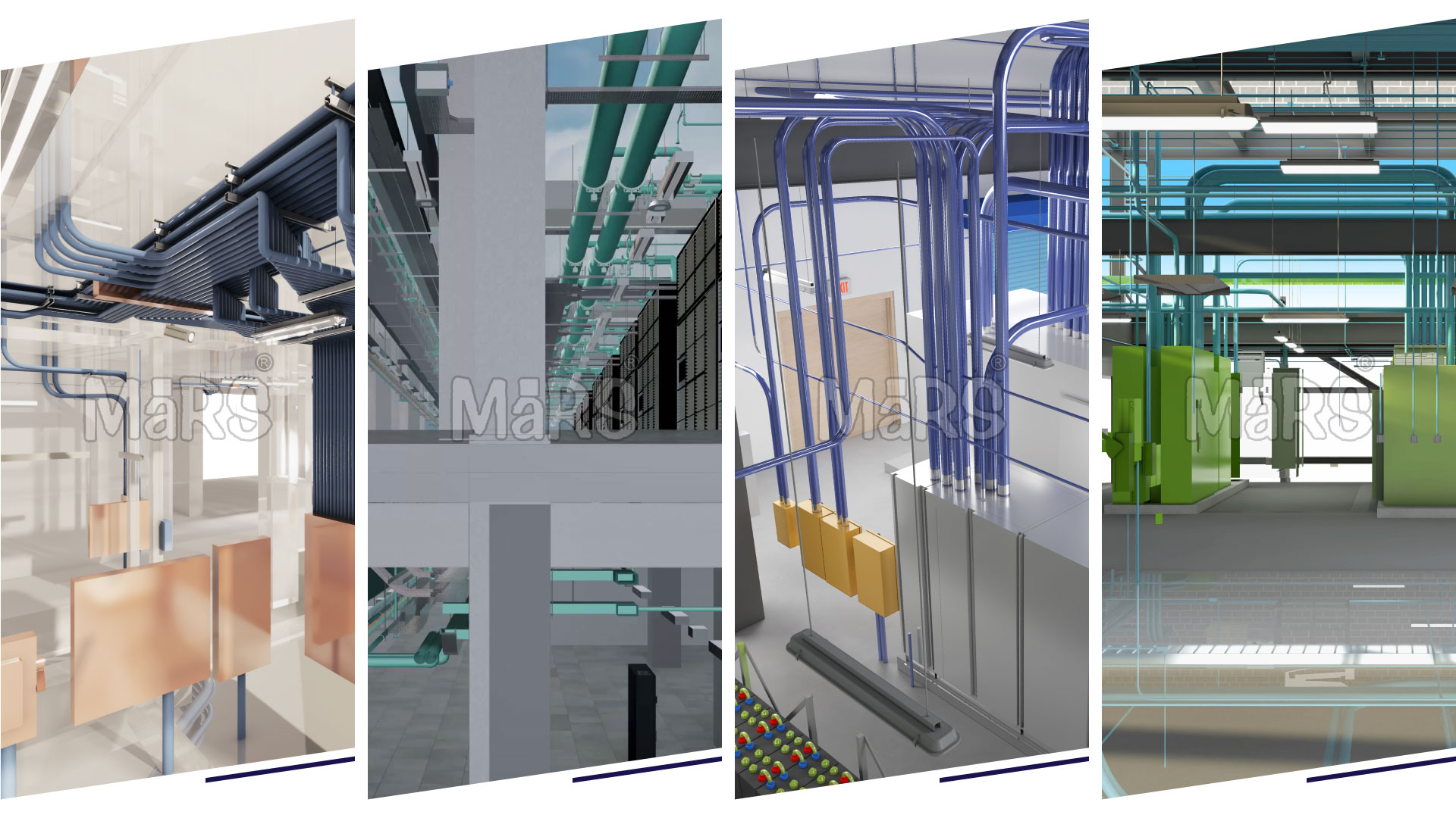
BIM models for projects with emergency power systems are often color-coded to distinguish normal power conduit (typically blue) from emergency power conduit (typically red) and critical branch circuits (typically orange or yellow). This color-coding makes separation violations immediately visible during coordination reviews and ensures that field teams can quickly identify circuit types during installation and inspection.
Generator Feeder Routing
Emergency generator feeders are among the largest and most physically demanding conduit runs on a complex project. Large-diameter conduit or bus duct running from a generator room or rooftop generator pad to the main switchboard or automatic transfer switch must navigate structural, mechanical, and architectural barriers across potentially significant distances.
BIM allows generator feeder routing to be planned and coordinated with all interfering systems before the conduit is ordered or installed. Structural penetration locations, required fire ratings for raceways penetrating rated assemblies, and coordination with fire and smoke damper locations can all be resolved in the model, avoiding the costly field surprises that are common when large feeder runs are planned from 2D drawings alone.
Electrical contractors who understand the value of early BIM involvement in these critical routing decisions are better positioned to deliver on schedule. Engaging in structured BIM coordination before breaking ground is one of the highest-return investments an electrical subcontractor can make on a complex project.
Conduit Routing Strategies for Building Renovations and Retrofits
Renovation projects present a fundamentally different set of conduit routing challenges compared to new construction. The existing building contains systems, structure, and spatial constraints that are not fully known until demolition reveals what is actually inside the walls and above the ceilings. Managing this uncertainty is one of the most important skills in renovation electrical work.
3D Laser Scanning and Point Cloud Integration
Laser scanning technology, also known as 3D reality capture, is increasingly used on renovation projects to create an accurate as-built record of existing conditions before design begins. A laser scanner captures millions of measurement points per second, generating a dense point cloud that represents the existing space in three dimensions.
That point cloud is imported into the BIM environment and used as the background reference against which new conduit routing is designed. Existing structural members, ductwork, piping, and ceiling systems are all visible in the point cloud, allowing the design team to route new conduit around existing constraints with the same precision that would be possible in new construction.
This approach dramatically reduces the number of unforeseen conditions that surface during construction, which are the primary driver of cost overruns on renovation projects. Hospital renovation projects in particular benefit from point cloud-based BIM coordination because work must be sequenced around active patient care areas where repeated disruptions are not acceptable.
Phased Installation and Temporary Power Routing
Renovation projects often require phased construction, where portions of a building remain occupied and operational while other areas are under renovation. Electrical conduit routing must account for temporary power feeds, temporary lighting circuits, and the sequencing of permanent system cutover.
BIM supports phased installation planning by allowing teams to model temporary and permanent systems simultaneously and visualize how the installation will be staged over time. Temporary power conduit routes that conflict with future permanent installations can be identified and resolved before temporary systems are installed, preventing the common situation where temporary conduit must be cut out and reinstalled to allow permanent work to proceed.
Electrical contractors who understand BIM are significantly better prepared to manage the complexity of phased renovation projects, where the cost of unplanned rework is compounded by the operational sensitivity of the occupied building.
Conclusion: BIM Is the Foundation of Efficient Conduit Routing
In complex buildings, electrical conduit routing is a coordination challenge as much as it is a technical one. From the type of conduit specified and the NEC requirements governing its installation, to the physical constraints of ceiling plenums shared with mechanical, plumbing, and structural systems, every routing decision carries risk. BIM provides the tools, the process, and the shared visual language that trade contractors and general contractors need to plan, coordinate, and execute conduit installations with precision and confidence.
Whether the project is a new hospital, a high-rise commercial tower, a data center, or a phased renovation of an occupied building, the principles of BIM-based conduit routing remain consistent: model early, coordinate completely, resolve conflicts before they reach the field, and use the model to drive prefabrication and installation efficiency.
Investing in professional electrical modeling and coordination before construction begins is not just a best practice. On complex projects in today’s market, it is a competitive requirement.