The effective tracking and control of Mechanical, Electrical, and Plumbing (MEP) components in a project is essential for minimizing construction costs. As-built status, however, is frequently restricted to assertions made by subcontractors and sporadic physical inspections, which can prove to be expensive and unnecessary for the majority of projects. Numerous solutions have been found to optimize MEP tracking; nevertheless, tracking MEP systems becomes challenging when on-site fabrication adjustments result in altered layouts from planned components.
MEP tracking also helps facility managers by streamlining maintenance tasks, monitoring asset performance, and increasing operational efficiency. It also gives BIM models vital information about equipment, maintenance schedules, and spare parts. According to a study by Bosche et al. (2014), an integrated approach of Scan to BIM is helpful for the automated tracking of MEP systems. A detailed discussion of how this updated Scan to BIM approach can enhance MEP Work Tracking in a project will be explored in the following article.
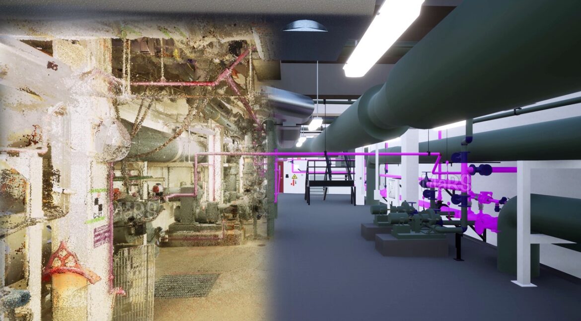
From Laser Scans to BIM
Fast, precise, and comprehensive 3D data regarding scanned scenes are provided by laser scanning technology. Millions of points are scanned in a single scan thanks to its ability to produce a dense 3D point cloud with millimeter-to-centimeter accuracy. In the construction industry and for facility maintenance, this technology is used by construction managers for quality control, facility management, and progress monitoring. Laser scanning is thought to be the best tool for gathering 3D information.

Scan-to-BIM, or recreating as-built 3D BIM models from 3D point clouds, is accomplished using laser scanning. 3D model objects can be automatically recognized and uniquely identified thanks to this procedure. BIM for MEP systems are essential for determining building costs and asset value. MEP components are more flexible to install in pipes and ducts than structural components, but their packed layouts, higher danger of occlusions, and other factors make tracking them difficult. For control and earned value measurement, it is essential to comprehend their as-built status.

Scan to BIM Process for optimizing work tracking of MEP components
The process, consisting of 3D point clouds that can be supplemented with digital photographs, is utilized in the scan-to-BIM process used for MEP system work tracking to process the current condition of the structure, as-built condition during construction, and as-is during operations. The following section explains how the use of this technology can improve the progress work tracking process of MEP components in a project:
1. Automated 3D Object Recognition Procedure
In this method, 3D point clouds are registered into the same coordinate system as the 3D model. Project survey points ought to be used for this procedure. Structural components can be utilized as substitute survey markers if the building structure is already under control. As-built objects are detectable in the combined point clouds when registration is finished. These clouds are divided into as-built, occluding, and as-planned point clouds. For object recognition, the corresponding as-planned, as-built, and occluding point clouds are collected and analyzed for each object.
The process looks for objects using previous geometric and semantic data from the most recent BIM model. The output is a list of recognized objects, along with their configurations and confidence ratings.

2. Automated Scan-to-BIM Procedure (Deviation Analysis)
The next step is an automatic Scan-to-BIM procedure that identifies objects of the MEP systems based on data acquired from the existing BIM model, such as expected object location and orientation and recognition results. In addition to information on differences between the as-built and as-designed BIM models—which may include displacements, deformations, or unexplained items—the procedure generates a list of identified objects of the MEP system with confidence levels.
3. Semi-automated BIM Model Rectification Procedure (Deviation Correction)
The BIM model is updated to the new, as-is state at the end of this procedure by rectifying any detected deviations in the components utilizing automated, semi-automated, or human workflows. The project’s Operations and Maintenance phase is when this step is most frequently used. The most challenging part of MEP components is the differences between the as-built and as-designed layouts caused by component fabrication occurring on-site. To update the model to its as-built state, deviation correction necessitates this step.
The procedure for monitoring MEP component work that has been described above should be followed for the lifecycle of the project. It should be started during the construction phase and can be utilized for asset management and maintenance even after construction until the operations and maintenance phase.
Related blog:
Scan To BIM Introduction – From Technology To The BIM Model
Conclusion
MEP systems play a significant role in the construction system, which impacts the project’s cost. Effective asset management requires both the as-built status of these components and automated, controlled progress tracking. However, as-built layouts for MEP components differ from intended layouts since they are created on-site. As a result, the Scan to BIM procedure covered in this article aids in asset management and maintenance and optimizes MEP construction progress.